RAID (Redundant Array of Inexpensive Disks) is a method to store data on multiple independent physical disks to improve performance or fault tolerance.

RAID Levels and Types
Physical disks merge to create what is called a virtual disk. This virtual disk appears to the host system as a single disk or logical drive.
For example, if you have physical disk 1 and physical disk 2 that make up a virtual RAID disk, these two disks are shown to the host system as a single disk.
Characteristics
RAID means a storage system that uses multiple hard drives or SSDs between which it distributes or replicates data.
Depending on your configuration, the advantages of a RAID on a single disk are one or more of the following high integrity, higher fault tolerance, higher efficiency, and increased capacity.
In its original applications, its main advantage was the ability to combine multiple low-cost devices and legacy technology in one package that offers more capacity, reliability, speed, or a combination of them than a single next-generation device and higher cost.
At the simplest level, a RAID combines multiple hard drives into one logical drive. So, instead of seeing a few different hard drives, the operating system only sees one.
RAIDs are often used on servers and are often implemented with disk drives of the same capacity.
Due to the drop in the price of hard drives and the increasing availability of RAID options available on motherboard chipsets, RAIDs are also an option on more advanced personal computers.
This is especially common on computers dedicated to demanding storage-intensive tasks such as video and audio editing.
The original RAID specification suggested a number of levels or different disk combinations. Each had theoretical advantages and disadvantages.
Different applications of this concept have emerged over the years. Many of them differ significantly from their original levels, but the habit of calling them by numbers has been preserved.
For example, this can be confusing as one RAID5 implementation can differ significantly from another. RAID3 and RAID4 levels are often mixed and even used interchangeably.
So its definition has been discussed for years, but as a result, the term redundant RAID0 is really a RAID.
Similarly, the transition from cheap to independent confuses many things about the intended purpose of RAID. There are even some implementations of the RAID concept that use a single disk.
However, in general, it is a system that uses basic concepts such as defragmenting physical disk space to increase reliability, capacity, or performance.
Development
Norman Ken Ouchi from IBM had a patent to recover data stored in a defective memory unit in 1978. This patent also mentions mirror copying, which will be called RAID1, and special parity calculation protection, which will later be called RAID4.
RAID technology was first described in 1987 by a group of computer scientists from the University of California, Berkeley. This group looked at the possibility of using two or more disks that appear as a single device for the system.
In 1988, RAID levels 1 to 5 were officially defined by David A. Patterson, Garth A. Gibson, and Randy H. Katz. And the term was first used in this experiment, which revealed the entire disk set industry.
Advantages
It provides fault tolerance, improves system performance, and increases productivity.
Failure Tolerance
It protects against data loss and provides real-time data recovery with intermittent access in the event of a disk failure.
Performance/Speed Improvement
A C drive consists of two or more hard drives that operate as a single device before the host system. The data is split into tracks written to multiple drives at the same time.
This process, called data partitioning, significantly increases storage capacity, and offers significant performance improvements. It improves system performance by allowing multiple drives to run in parallel.
Greater Reliability
RAID solutions use two techniques to increase reliability data redundancy and parity information. Redundancy involves storing the same data on multiple volumes.
The second approach to data protection is to use data parity. Parity uses a mathematical algorithm to describe the data in a unit. When a drive fails, the remaining correct data is read and compared with parity data stored by the array.
High Availability
Increases uptime and network availability. To avoid downtime, data should be accessible at any time. Data availability is divided into two directions: data integrity and fault tolerance. Data integrity refers to the ability to obtain sufficient data at any time.
Most RAID solutions offer dynamic sector repair that instantly repairs bad sectors due to software errors. The second aspect of usability, fault tolerance, is the ability to keep data available in case of one or more system failures.
Applications
The distribution of data on multiple disks can be managed by special hardware or software. There are also hybrid RAID systems based on specific software and hardware.
In software distribution, disk drives in the array are managed by the operating system through a normal disk controller (IDE/ATA, SATA, SCSI, SAS, or Fiber Channel).
It is traditionally considered to be a slower solution, it may be faster than some hardware applications at the expense of modern CPUs and less processing time for other system tasks.
A hardware-based RAID application requires at least one custom RAID controller integrated as an independent expansion card or on the motherboard, managing disk management, and performing parity calculations.
This option generally offers better performance and facilitates the support of the operating system. Hardware-based applications often support hot-swapping and allow replacement of faulty disks without having to stop the system.
In larger RAIDs, controllers and disks are usually mounted in a specific external enclosure that connects to the host using one or more SCSI, Fiber Channel, or iSCSI connections. Sometimes the RAID system is completely autonomous and connects to the rest of the system as NAS.
Hybrid RAIDs have become very popular with the release of cheap hardware RAID controllers. In fact, it is a normal disk controller without hardware RAID capability, but the system includes a low-level application that allows users to create BIOS-controlled RAIDs.
To recognize the controller as a single RAID device, you must use a specific device driver for the operating system.
These systems actually do the entire calculation with software, that is, the CPU, ultimately with performance loss, and are usually limited to a single disk controller.
An important feature of hardware RAID systems is that they can add a non-volatile write cache that provides increased disk set performance without sacrificing data integrity in case of system failure.
This feature cannot be used explicitly in software systems that cause the problem of rebuilding the disk set when the system restarts after failing to maintain data integrity.
In contrast, software-based systems are much more flexible, and hardware-based systems add more fault points to the system.
All applications can support the use of one or more hot spare disks, pre-installed drivers that can be used immediately after a disk failure. This shortens rebuild time and reduces repair time.
What are RAID Types?
RAID 0 (Data Striping – No Mirror – No Parity)
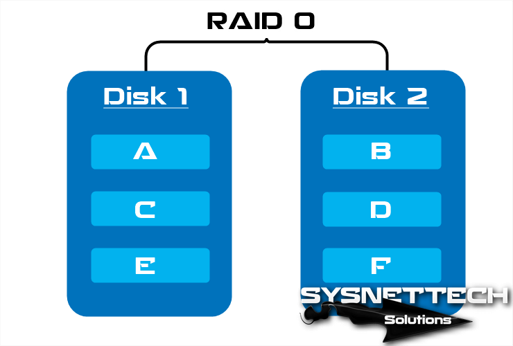
A RAID 0 (also known as a split set or split volume) distributes data evenly between two or more disks without redundant parity information and is not redundant.
It is normally used to improve performance and creates a small number of large virtual disks from a large number of small physical disks.
It can be created with disks of different sizes, but the storage space added to the set will be limited to the size of the smallest disc.
Useful for configurations like NFS read-only servers, where plugging in many disks is time-consuming and redundancy is unimportant.
Another use is to limit the number of disks by the operating system, so RAID 0 is a way to use more disks in Windows 2000 Professional, and then it is possible to mount the partitions in Unix-like directories, so you eliminate the need for an assignment.
For example, when you configure two 1TB disks in RAID0 mode, you will have a total of 2TB of storage, and since this mode has no redundancy, your disk performance will be doubled.
Result> Performance: Excellent, Redundancy: No, Disk Requirement: Minimum of 2
JBOD (Linear RAID)
Although not one of the numbered RAID types, it is a popular method of defragmenting multiple physical hard drives into one virtual disk, JBOD uses two or more physical disks to create a logical drive.
JBOD is useful for systems that do not support LVM/LSM, such as Microsoft Windows, but Windows 2003 Server, Windows XP Pro, and Windows 2000 support JBOD through software called dynamic disk spreading.
RAID 1 (Data Mirroring – No Stripe – No Parity)
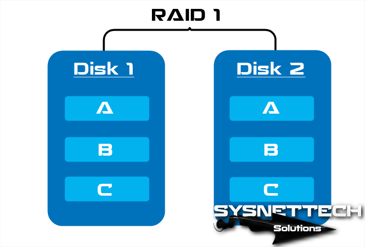
RAID 1 creates an exact copy of the dataset on two or more disks.
It consists of two mirrored disks that increase reliability exponentially compared to a single disk, meaning the cluster’s probability of failure is equal to the product of each disk’s failure probabilities.
Reading performance increases approximately as a linear multiple of the number of copies, it may be reading two different data on two different disks at the same time, so its performance doubles.
To maximize the performance advantages of RAID 1, it is recommended to use separate disk controllers, one for each disk.
The average reading time decreases because sectors to be searched can be split across disks, reducing the search time and increasing the transfer speed by the single limit of the speed supported by the RAID controller.
Since the data must be written to all disks, the cluster behaves like a single disk. Therefore, performance does not improve.
For example, if you have 2 1TB disks, when you configure them with RAID1, your total storage space will still be 1TB. In this mode, since data security is addressed, data written to disk 1 will be written to the other disk by mirroring.
Result> Performance: Great, Redundancy: Excellent, Disk Requirement: Minimum of 2
RAID 2 (Bit Level Striping)
RAID2 splits data at the bit level instead of the block level and uses the Hamming code for error correction (ECC). Discs are synchronized by the controller to work together.
This is the only original level that is not currently used and allows extremely high transfer speeds.
Theoretically, this mod will need 39 disks in a modern computer system: 32 will be used to store the separate bits that make up each word and 7 will be used for error correction.
In the image below, A1, B1, C1, and D1 are bits, Ap1, Bp2, Cp2, and Dp2 are error correction codes. When writing data to discs, ECC code is calculated and data bits are written to data discs. ECC codes are written to other ECC disks.
When the data is read again, ECC codes are also checked from ECC disks, thereby verifying the data integrity.
Many discs can be used in this mode but standard applications are;
- Data Disk: 4 = ECC: 3
- Data Disk: 10 = ECC: 4
This mode is very expensive and is not used because the application process is complicated.

RAID 3 (Byte Level Striping)
Although RAID3 works like RAID0, it uses a byte-level partition with a special parity disk and is rarely used in practice.
One of its side effects is that it is normally not able to participate in several simultaneous requests because, by definition, any simple data block will be divided by all members of the cluster, the same address resides within each of them.
Therefore, any read or write operation requires the activation of all disks in the cluster.
In the image below, A1, A2, A3, A4, A5, A6, B1, B2, B3, B4, B5, B6 are bytes and the other disk are parities. This mode performs well for sequential read and write, and low read and write speeds.

RAID 4 (Block Level Striping)
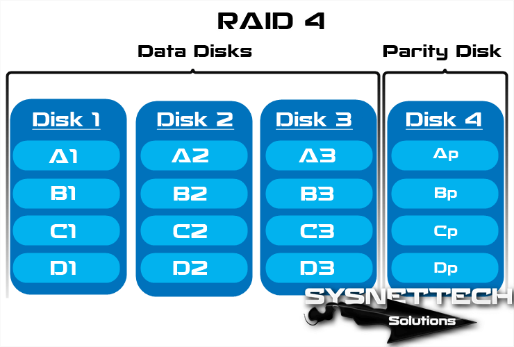
This level uses block-level striping with a special parity disc. It requires at least 3 physical disks and is similar but different from RAID3 and RAID5 except that it is allocated at the block level instead of byte level.
This allows each member of the set to work independently when a single block is requested.
If the disk controller allows this, a RAID4 set can offer multiple read requests simultaneously.
In principle, it will also be possible to present several write requests at the same time, but since all parity information is on one disc, it will become the bottleneck of this set.
In the image below, A1, B1, C1, and D1 are blocks, and Ap, Bp, Cp, and Dp are parities.
RAID 5 (Block Level Striping – Distributed Parity)
A level uses block-level data splitting by distributing parity information across all member disks in the cluster.
It also became popular thanks to its low redundancy cost, applied with hardware support to calculate parity.
At least three disk drives need to be applied, and failure of a second disk will result in complete data loss.
The maximum number of disks in the redundancy group is theoretically unlimited, but in practice it is common to limit the number of drives.
The disadvantages of using more redundancy groups are that the two discs are likely to fail at the same time, longer rebuild time, and a higher chance of finding an unrecoverable sector during the rebuild.
As the number of disks increases at this level, MTBF (Mean Time Between Failures) may be lower than a single disc. This level shows poor performance when exposed to workloads that contain text that is smaller than the tape size.
This is because the parity needs to be updated for each write that requires read, change, and write sequences for both the data block and parity block.
More complex applications often include non-volatile caches to reduce this performance issue.
In the event of a system malfunction with writings enabled, the parity of a partition strip may be left inconsistent with the data.
If this is not detected and repaired without a disk or block failing, data may be lost because an incorrect parity will be used to rebuild the lost block in this section.
This vulnerability is known as the write-hole. It is common to use non-volatile caches and other techniques to reduce the possibility of this vulnerability.

RAID 6
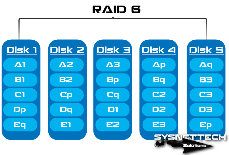
RAID6 expands the RAID5 level by adding another parity block, so it divides the data at the block level and distributes the two parity blocks among all members of the set. In fact, this level was not one of the original RAID levels.
This can be considered as a special case of the Reed-Solomon code and only requires sums in the Galois field. It is the Galois binary field used because it works on bits.
In cyclic representations of Galois binary fields, the total is calculated with a simple XOR. At this level, the parity spreads along the strips, the parity blocks are located in a different place in each slice.
It is inefficient when fewer disks are used, but as the set grows and more disks become available, the loss of storage capacity becomes less important, increasing the likelihood of two disks failing simultaneously.
It provides protection against double disk failure and error when rebuilding the disk.
If we only have one set, it might be more convenient than using a RAID5 with a spare disk. The data capacity of the RAID6 set is n-2, where n is the total number of disks in the set.
It does not degrade the performance of reading operations but degrades the performance of write operations due to the action required by additional parity calculations.
This drop can be minimized by grouping write operations that can be performed using a WAFL file system in as few lines as possible.
In the image below, A, B, C, D, and E are blocks, others, Ap, and Aq values are parities. These Ap and Aq values can handle two disk errors.
RAID 5E ve RAID 6E
RAID 5 and RAID 6 variants with spare disks are often called RAID 5E and RAID 6E.
These disks can be connected and be in ready or standby mode. In RAID 5E and RAID 6E, backup disks can be used by any of the member drives.
They do not mean any performance enhancements, but they minimize rebuild time and management work when malfunctions occur.
The spare disk is not really part of the kit until a disk fails and the set is put back on the spare part.
Nested RAID levels
RAID 0+1
RAID 0+1, also known as RAID 01, should not be confused with RAID1. This level is used to duplicate and share data between multiple disks. In short, the disk is a mirror.
When one hard drive fails, the lost data can be copied from the other 0 levels to reconstruct the overall set. It cannot tolerate two simultaneous disk errors unless it is in the same partition.
Given these increased risks from RAID 0+1, many critical business environments are beginning to consider more fault-tolerant RAID configurations that add an underlying parity mechanism.
Among the most promising are hybrid approaches such as RAID 0+1+5 (mirror on single parity) or RAID 0+1+6 (mirror on double parity) and are the most common by companies.
RAID 1+0
A RAID 1+0, sometimes called RAID 10, is like a 0+1, except that the levels that make it upside down are a mirror partition of RAID 10.
In each RAID 1 partition, all but one disk can fail without data loss. However, if the failed disks are not replaced, the remaining disks become a single point of failure for the entire set. If this disk fails, all data in the entire cluster is lost.
If a faulty disk is not replaced, a single unrecoverable media error on the mirrored disk will result in data loss.
RAID 10 is often the best choice for high-performance databases because the absence of parity calculations provides faster write speeds.
RAID 30
RAID 30 or partition with special parity set is a combination of RAID 3 and RAID 0. RAID 30 provides high transfer speeds with high reliability with high application costs.
RAID 30 splits the data into smaller blocks and divides it into each RAID 3 set, which divides it into smaller pieces, applies an XOR to each, calculates the parity, and writes to all disks in the cluster except one, and stores parity information.
The size of each block is decided when creating RAID.
RAID 30 allows one disk in each RAID 3 set to fail. Until these faulty disks are replaced, the other disks in each cluster are unique fault points for the entire RAID 30 cluster.
RAID 100
RAID100, sometimes called RAID10 + 0, is part of the RAID10 sets. RAID100 is an example of “grid RAID”, a RAID in which split clusters themselves are reassembled.
The main benefits of RAID100 over a single RAID level are better performance for random readings and reduction of risky hotspots in the pool.
For these reasons, RAID100 is generally the best choice for very large databases, where the basic software set limits the number of physical disks allowed in each standard set. Applying nested RAID levels allows you to virtually remove the physical drive limit on a single logical volume.
RAID 50
A RAID 50, sometimes called RAID5+0, combines the block level division of a RAID 0 with the distributed parity of a RAID 5, so it is a cluster of RAID 0 divided from RAID5 elements.
A disk in each RAID5 set can fail without data loss. However, if the failed disk is not replaced, the remaining disks in this cluster become a single point of failure for the entire cluster.
If one fails, all data in the global setting will be lost. The time it takes to recover represents a period of vulnerability.
The RAID50 improves the performance of RAID5, especially in writing, and provides better fault tolerance than a single level.
This level is recommended for applications that require high fault tolerance, capacity, and random search performance. As the number of drives in the RAID50 set increases and the capacity of the disks increases, the recovery time also increases.
Proprietary RAID Levels
Double Parity
A frequent addition to existing RAID levels is double parity, sometimes applied and known as diagonal parity.
As with RAID6, there are two sets of parity control information, but in contrast, the second set is not another set of points calculated for a different polynomial syndrome for the same data block groups, but an extra parity is calculated from a different group.
Due to the low performance of the dual parity system, it is not recommended to work in degraded mode.
RAID 1.5
This is a proprietary HighPoint level, sometimes called RAID15. From the limited information available, it seems to be an accurate implementation of RAID1.
When read, the data is taken from both disks simultaneously, and most of the work is done on the hardware instead of the software driver.
RAID 7
RAID7 is a registered trademark of Storage Computer Corporation and adds cache to RAID3 or RAID4 to improve performance.
RAID S or Parity RAID
This level is the proprietary distributed parity system of EMC Corporation used in Symmetrix storage systems. Each volume is located on a single physical disk and multiple volumes are optionally combined for parity calculation.
EMC initially named this feature RAID-S, and later renamed Parity-RAID for the Symmetrix DMX platform. EMC also currently offers a standard RAID5 for Symmetrix DMX. Completed with 3.4 mega tripods.
Matrix RAID
This is a feature that first appears in the Intel ICH6R RAID-BIOS. It uses two or more physical disks that separate portions of the same size, each of the different levels.
For example, 200 of 4 disks of 600 GB in total can be used in 200 RAID0, 200 in RAID10, and 200 in RAID5. Currently, most other RAID-BIOS products only join a single set of a disk.
This product is intended for home users, providing a secure area for documents and other files you want to keep as backup and a faster area for operating system applications.
Linux MD RAID 10
The Linux kernel software can be used to create a classic RAID1+0 array, but it also allows a single RAID10 level with some interesting extensions. In particular, it supports mirroring of k blocks in n units when it cannot be divided by k n.
This is done by repeating each block by writing to then drive at the bottom. Obviously this is equivalent to the standard RAID10 configuration.
Linux also allows you to create other configurations using the MD controller in addition to other uses such as multipath storage and LVM2.
IBM ServeRAID 1E
The IBM ServeRAID adapter series supports double reflection of an optional number of drives, as shown in the graphic.
This configuration is fault-tolerant for non-contiguous drives. Other storage systems such as Sun’s StorEdge T3 also support this mode.
RAID Z
Sun Microsystems’ ZFS file system implements a built-in backup scheme similar to RAID5 called RAID-Z.
This configuration avoids the need for a read-change-write stream by mirroring small blocks instead of protecting small blocks with parity calculation, by performing only full-pane write operations for RAID5 write hole and small write operations. This knows the file system underlying storage structure and can manage additional space as needed.
Related Articles
♦ What is NTFS?
♦ BIOS (Basic Input/Output System)
♦ What is a Modem?
♦ What is Chipset?
♦ What is USB Socket?


