
The Spanning Tree Protocol (STP) in computer networking stops loops in the network setup. It’s vital for keeping the network stable and preventing broadcast storms. It works by specifying a single “root” bridge and then turning off connections that might cause loops. So, STP is a protocol we commonly use. However, it can be a little tricky to configure.
In this article, we’ll show you how to configure the Spanning Tree Protocol on a Layer 2 Switch. We’ll use GNS3, a network simulation tool, to do it. We’ll look at essential features like PortFast, BPDU guard, and root guard. After that, we’ll show you how to set it up to work with VPCS computers.
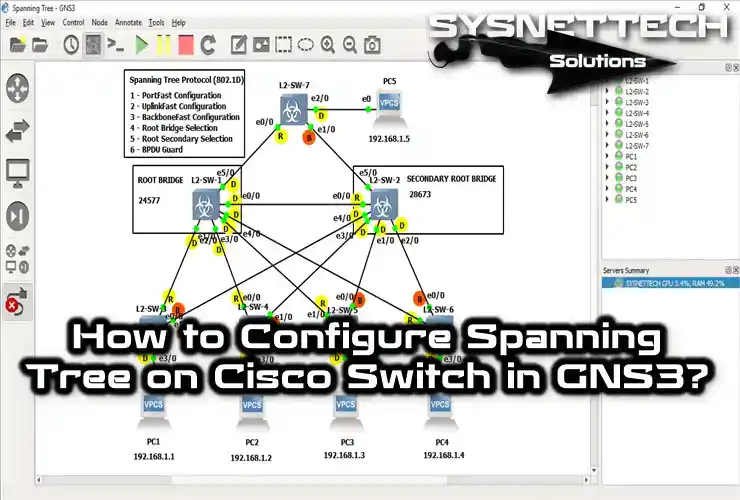
How to Build Spanning Tree Protocol (STP) on Layer 2 Switch using GNS3
When you’re setting up Spanning Tree Protocol, you need to turn on certain features to make sure it works well. If you’re using old Cisco Switches, they might still be using the old STP protocol, too. In this case, turn on portfast, BPDU guard, and root guard. These features make the Standard STP protocol work better.
When you’re setting up 802.1D on Cisco Switches, think about features that make STP work better and faster. These improvements really boost how well Layer 2 works.
PortFast term, UplinkFast term, and BackboneFast feature are significant for making networks run well. Turning them on makes things happen faster, which makes the LAN work better.
Portfast makes connections faster by skipping some steps. BPDU guard stops unauthorized switches, which helps avoid LAN loops. Root guard stops unauthorized switches from becoming the main one, which keeps the network stable. In short, turning on these features helps make sure your LAN runs smoothly and works well.
In our previous articles, we’ve talked about setting up different Spanning Tree Protocol (STP) features in GNS3. These include PortFast configuration, UplinkFast configuration, and BackboneFast configuration. Now, in this article, we’ll bring all these STP features together and set them up to work with each other.
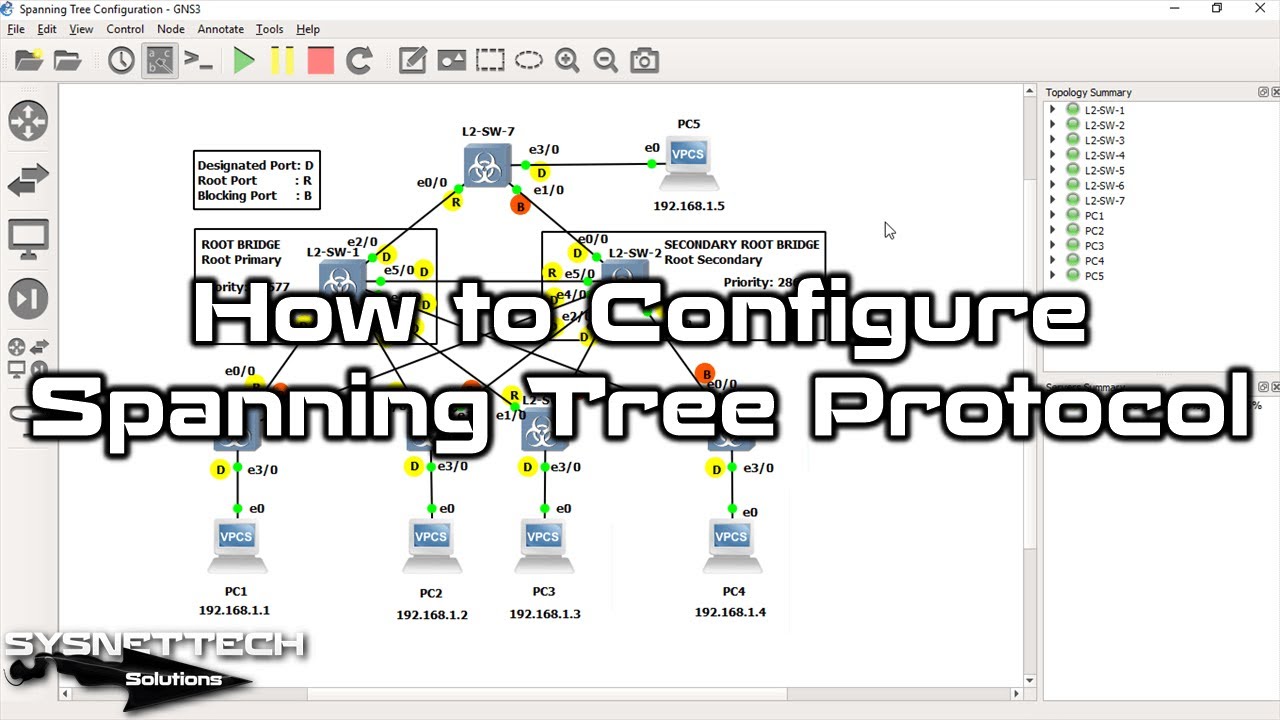
How to Configure Spanning Tree
I suggest using Virtual PCs (VPCS) to make sure the STP setup goes well. Using a VM might put too much strain on your PC for this project. So, to help you configure virtual Switches better, I’ll use VPCS in this article.
Steps:
Step 1
First, create a new project on the GNS3 simulator software.

Step 2
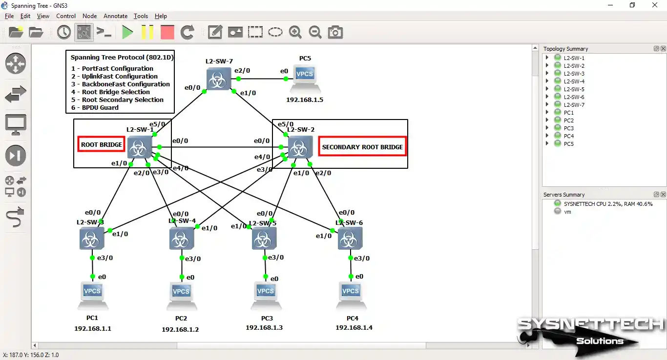
After adding the L2 Switch to the GNS3 program, create a redundant network topology as in the image below.

Step 3
Configure the TCP/IP configuration of the GNS3 VPCS computers and then test the network connection between them by pinging VPCS PC1 to VPCS PC5.

1) How to Choose Root Bridge
In the following LAN topology, a Root Bridge selection in the network distribution layer makes sense. And configure the Secondary Root Bridge Switch as in step 1, which will be activated if there is an error in the Root Bridge Switch.
Step 1
Specify the Root Bridge Switch and Secondary Root Bridge for the following LAN topology.
Step 2
Configure Cisco Switch L2-SW1 as the Root Bridge and configure L2-SW-2 Switch as the Secondary Root Bridge.
Priority values are taken into consideration when selecting a manual Root Bridge. You can configure this process in two ways;
- You can configure it using the
spanning-tree vlan 1 prioritycommand. - You can configure it using the
spanning-tree vlan 1 rootcommand.
In this article, we will use the Root Primary command to select the Root Bridge. To select L2-SW-1 as Root Bridge, use the command below and then check with the show spanning-tree command.
L2-SW-1#conf t
Enter configuration commands, one per line.  End with CNTL/Z.
L2-SW-1(config)#
L2-SW-1(config)#spanning-tree vlan 1 root primary
L2-SW-1(config)#exit
L2-SW-1#
*Sep 27 17:18:03.648: %SYS-5-CONFIG_I: Configured from console by console
L2-SW-1#
L2-SW-1#show spanning-tree

VLAN0001
  ST enabled protocol ieee
  Root ID    Priority    24577
             Address     003f.181f.4800
             This bridge is the root
             Hello Time   2 sec  Max Age 20 sec  Forward Delay 15 sec

  Bridge ID  Priority    24577  (priority 24576 sys-id-ext 1)
             Address     003f.181f.4800
             Hello Time   2 sec  Max Age 20 sec  Forward Delay 15 sec
             Aging Time  15  sec

Interface           Role Sts Cost      Prio.Nbr Type
------------------- ---- --- --------- -------- --------------------------------
Gi0/0               Desg FWD 4         128.1    Shr
Gi0/1               Desg FWD 4         128.2    Shr
Gi0/2               Desg FWD 4         128.3    Shr
Gi0/3               Desg FWD 4         128.4    Shr
Gi1/0               Desg FWD 4         128.5    Shr
Gi1/1               Desg FWD 4         128.6    Shr


L2-SW-1#

Step 3
To configure the Cisco Switch L2-SW-2 as a Secondary Root Bridge, use the following command and then check the Priority value of the L2-SW-2 Switch.
L2-SW-2#conf t
Enter configuration commands, one per line.  End with CNTL/Z.
L2-SW-2(config)#
L2-SW-2(config)#spanning-tree vlan 1 root secondary
L2-SW-2(config)#exit
L2-SW-2#
L2-SW-2#show spanning-tree

VLAN0001
  ST enabled protocol ieee
  Root ID    Priority    24577
             Address     003f.181f.4800
             Cost        4
             Port        1 (GigabitEthernet0/0)
             Hello Time   2 sec  Max Age 20 sec  Forward Delay 15 sec

  Bridge ID  Priority    28673  (priority 28672 sys-id-ext 1)
             Address     003f.18b2.5800
             Hello Time   2 sec  Max Age 20 sec  Forward Delay 15 sec
             Aging Time  300 sec

Interface           Role Sts Cost      Prio.Nbr Type
------------------- ---- --- --------- -------- --------------------------------
Gi0/0               Root FWD 4         128.1    Shr
Gi0/1               Desg FWD 4         128.2    Shr
Gi0/2               Desg FWD 4         128.3    Shr
Gi0/3               Desg FWD 4         128.4    Shr
Gi1/0               Desg FWD 4         128.5    Shr
Gi1/1               Desg FWD 4         128.6    Shr


L2-SW-2#

2) How to Set Port Status
In our previous articles, we examined how STP works. Now, let’s look at the Port Status of Cisco Switches by following the steps below.
Step 1
At the L2-SW-2 Switch CLI prompt, execute the show spanning-tree command and define the Designated, Root, and Blocked port states.
L2-SW-2#show spanning-tree

VLAN0001
  ST enabled protocol ieee
  Root ID    Priority    24577
             Address     003f.181f.4800
             Cost        4
             Port        1 (GigabitEthernet0/0)
             Hello Time   2 sec  Max Age 20 sec  Forward Delay 15 sec

  Bridge ID  Priority    28673  (priority 28672 sys-id-ext 1)
             Address     003f.18b2.5800
             Hello Time   2 sec  Max Age 20 sec  Forward Delay 15 sec
             Aging Time  300 sec

Interface           Role Sts Cost      Prio.Nbr Type
------------------- ---- --- --------- -------- --------------------------------
Gi0/0               Root FWD 4         128.1    Shr
Gi0/1               Desg FWD 4         128.2    Shr
Gi0/2               Desg FWD 4         128.3    Shr
Gi0/3               Desg FWD 4         128.4    Shr
Gi1/0               Desg FWD 4         128.5    Shr
Gi1/1               Desg FWD 4         128.6    Shr


L2-SW-2#

Step 2
Cisco Switch L2-SW-3 shows command output;
L2-SW-3#show spanning-tree

VLAN0001
  ST enabled protocol ieee
  Root ID    Priority    24577
             Address     003f.181f.4800
             Cost        4
             Port        1 (GigabitEthernet0/0)
             Hello Time   2 sec  Max Age 20 sec  Forward Delay 15 sec

  Bridge ID  Priority    32769  (priority 32768 sys-id-ext 1)
             Address     003f.18f9.da00
             Hello Time   2 sec  Max Age 20 sec  Forward Delay 15 sec
             Aging Time  300 sec

Interface           Role Sts Cost      Prio.Nbr Type
------------------- ---- --- --------- -------- --------------------------------
Gi0/0               Root FWD 4         128.1    Shr
Gi0/1               Altn BLK 4         128.2    Shr
Gi0/2               Desg FWD 4         128.3    Shr
Gi0/3               Desg FWD 4         128.4    Shr


L2-SW-3#

Step 3
Cisco Switch L2-SW-4 shows command output;
L2-SW-4#show spanning-tree

VLAN0001
  ST enabled protocol ieee
  Root ID    Priority    24577
             Address     003f.181f.4800
             Cost        4
             Port        1 (GigabitEthernet0/0)
             Hello Time   2 sec  Max Age 20 sec  Forward Delay 15 sec

  Bridge ID  Priority    32769  (priority 32768 sys-id-ext 1)
             Address     003f.18f0.f400
             Hello Time   2 sec  Max Age 20 sec  Forward Delay 15 sec
             Aging Time  300 sec

Interface           Role Sts Cost      Prio.Nbr Type
------------------- ---- --- --------- -------- --------------------------------
Gi0/0               Root FWD 4         128.1    Shr
Gi0/1               Altn BLK 4         128.2    Shr
Gi0/2               Desg FWD 4         128.3    Shr
Gi0/3               Desg FWD 4         128.4    Shr


L2-SW-4#

Step 4
Cisco Switch L2-SW-5 shows command output;
L2-SW-5#show spanning-tree

VLAN0001
  ST enabled protocol ieee
  Root ID    Priority    24577
             Address     003f.181f.4800
             Cost        4
             Port        2 (GigabitEthernet0/1)
             Hello Time   2 sec  Max Age 20 sec  Forward Delay 15 sec

  Bridge ID  Priority    32769  (priority 32768 sys-id-ext 1)
             Address     003f.183a.3300
             Hello Time   2 sec  Max Age 20 sec  Forward Delay 15 sec
             Aging Time  300 sec

Interface           Role Sts Cost      Prio.Nbr Type
------------------- ---- --- --------- -------- --------------------------------
Gi0/0               Altn BLK 4         128.1    Shr
Gi0/1               Root FWD 4         128.2    Shr
Gi0/2               Desg FWD 4         128.3    Shr
Gi0/3               Desg FWD 4         128.4    Shr


L2-SW-5#

Step 5
Cisco Switch L2-SW-6 shows command output;
L2-SW-6#show spanning-tree

VLAN0001
  ST enabled protocol ieee
  Root ID    Priority    24577
             Address     003f.181f.4800
             Cost        4
             Port        2 (GigabitEthernet0/1)
             Hello Time   2 sec  Max Age 20 sec  Forward Delay 15 sec

  Bridge ID  Priority    32769  (priority 32768 sys-id-ext 1)
             Address     003f.18a0.2400
             Hello Time   2 sec  Max Age 20 sec  Forward Delay 15 sec
             Aging Time  300 sec

Interface           Role Sts Cost      Prio.Nbr Type
------------------- ---- --- --------- -------- --------------------------------
Gi0/0               Altn BLK 4         128.1    Shr
Gi0/1               Root FWD 4         128.2    Shr
Gi0/2               Desg FWD 4         128.3    Shr
Gi0/3               Desg FWD 4         128.4    Shr


L2-SW-6#

Step 6
Cisco Switch L2-SW-7 shows command output;
L2-SW-7#show spanning-tree

VLAN0001
  ST enabled protocol ieee
  Root ID    Priority    24577
             Address     003f.181f.4800
             Cost        4
             Port        1 (GigabitEthernet0/0)
             Hello Time   2 sec  Max Age 20 sec  Forward Delay 15 sec

  Bridge ID  Priority    32769  (priority 32768 sys-id-ext 1)
             Address     003f.1870.d400
             Hello Time   2 sec  Max Age 20 sec  Forward Delay 15 sec
             Aging Time  15  sec

Interface           Role Sts Cost      Prio.Nbr Type
------------------- ---- --- --------- -------- --------------------------------
Gi0/0               Root FWD 4         128.1    Shr
Gi0/1               Altn BLK 4         128.2    Shr
Gi0/2               Desg FWD 4         128.3    Shr
Gi0/3               Desg FWD 4         128.4    Shr


L2-SW-7#

3) How to Configure PortFast
To configure STP PortFast on Cisco Switches, use the following commands on the Switch interfaces to which VPCS PCs are connected, and check the PortFast configuration with the show running-config | begin interface GigabitEthernet0/3 command.
The purpose of PortFast configuration in Layer 2 Switches is to ensure that interfaces configured as PortFast from STP Convergence processing are not processed during BPDU packet exchange.
Step 1
Cisco Switch L2-SW-3 Spanning Tree PortFast configuration process;
L2-SW-3#conf t
Enter configuration commands, one per line.  End with CNTL/Z.
L2-SW-3(config)#interface gigabitethernet0/3
L2-SW-3(config-if)#spanning-tree portfast
%Warning: portfast should only be enabled on ports connected to a single
 host. Connecting hubs, concentrators, switches, bridges, etc... to this
 interface  when portfast is enabled, can cause temporary bridging loops.
 Use with CAUTION

%Portfast has been configured on GigabitEthernet0/3 but will only
 have effect when the interface is in a non-trunking mode.
L2-SW-3(config-if)#exit
L2-SW-3(config)#exit
L2-SW-3#
*Sep 27 17:40:32.880: %SYS-5-CONFIG_I: Configured from console by console
L2-SW-3#show run | begin interface GigabitEthernet0/3
interface GigabitEthernet0/3
 media-type rj45
 negotiation auto
 spanning-tree portfast
!

Step 2
Cisco Switch L2-SW-4 PortFast configuration process;
L2-SW-4#conf t
Enter configuration commands, one per line.  End with CNTL/Z.
L2-SW-4(config)#interface gigabitethernet0/3
L2-SW-4(config-if)#spanning-tree portfast
%Warning: portfast should only be enabled on ports connected to a single
 host. Connecting hubs, concentrators, switches, bridges, etc... to this
 interface  when portfast is enabled, can cause temporary bridging loops.
 Use with CAUTION

%Portfast has been configured on GigabitEthernet0/3 but will only
 have effect when the interface is in a non-trunking mode.
L2-SW-4(config-if)#exit
L2-SW-4(config)#exit
L2-SW-4#
*Sep 27 17:41:23.448: %SYS-5-CONFIG_I: Configured from console by console
L2-SW-4#show run | begin interface GigabitEthernet0/3
interface GigabitEthernet0/3
 media-type rj45
 negotiation auto
 spanning-tree portfast
!

Step 3
Cisco Switch L2-SW-5 PortFast operation;
L2-SW-5#conf t
Enter configuration commands, one per line.  End with CNTL/Z.
L2-SW-5(config)#interface gigabitethernet0/3
L2-SW-5(config-if)#spanning-tree portfast
%Warning: portfast should only be enabled on ports connected to a single
 host. Connecting hubs, concentrators, switches, bridges, etc... to this
 interface  when portfast is enabled, can cause temporary bridging loops.
 Use with CAUTION

%Portfast has been configured on GigabitEthernet0/3 but will only
 have effect when the interface is in a non-trunking mode.
L2-SW-5(config-if)#exit
L2-SW-5(config)#exit
L2-SW-5#
*Sep 27 17:44:49.861: %SYS-5-CONFIG_I: Configured from console by console
L2-SW-5#show run | begin interface GigabitEthernet0/3
interface GigabitEthernet0/3
 media-type rj45
 negotiation auto
 spanning-tree portfast
!

Step 4
Cisco Switch L2-SW-6 PortFast operation;
L2-SW-6#conf t
Enter configuration commands, one per line.  End with CNTL/Z.
L2-SW-6(config)#interface gigabitethernet0/3
L2-SW-6(config-if)#spanning-tree portfast
%Warning: portfast should only be enabled on ports connected to a single
 host. Connecting hubs, concentrators, switches, bridges, etc... to this
 interface  when portfast is enabled, can cause temporary bridging loops.
 Use with CAUTION

%Portfast has been configured on GigabitEthernet0/3 but will only
 have effect when the interface is in a non-trunking mode.
L2-SW-6(config-if)#exit
L2-SW-6(config)#exit
L2-SW-6#
*Sep 27 17:45:26.583: %SYS-5-CONFIG_I: Configured from console by console
L2-SW-6#show run | begin interface GigabitEthernet0/3
interface GigabitEthernet0/3
 media-type rj45
 negotiation auto
 spanning-tree portfast
!

Step 5
L2-SW-7 PortFast operation;
L2-SW-7#conf t
Enter configuration commands, one per line.  End with CNTL/Z.
L2-SW-7(config)#interface gigabitethernet0/2
L2-SW-7(config-if)#spanning-tree portfast
%Warning: portfast should only be enabled on ports connected to a single
 host. Connecting hubs, concentrators, switches, bridges, etc... to this
 interface  when portfast is enabled, can cause temporary bridging loops.
 Use with CAUTION

%Portfast has been configured on GigabitEthernet0/2 but will only
 have effect when the interface is in a non-trunking mode.
L2-SW-7(config-if)#exit
L2-SW-7(config)#exit
L2-SW-7#
*Sep 27 17:55:22.994: %SYS-5-CONFIG_I: Configured from console by console
L2-SW-7#show run | begin interface GigabitEthernet0/2
interface GigabitEthernet0/2
 media-type rj45
 negotiation auto
 spanning-tree portfast
!

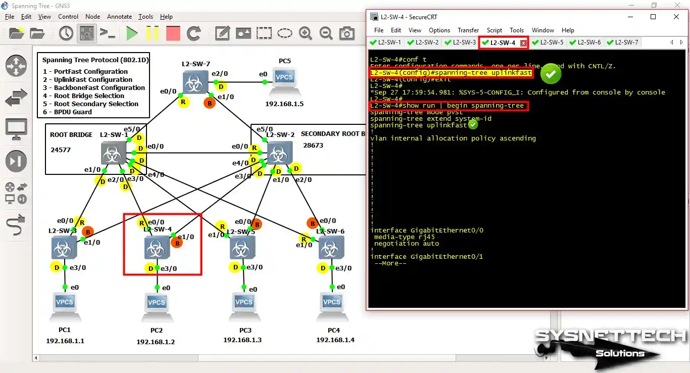
4) How to Configure UplinkFast
The purpose of UplinkFast configuration on Layer 2 Switches is to enable the switching of Blocking Port state interfaces to Forwarding Mode immediately in case of a link failure.
In the config mode of Switches with Blocking Port status in the network topology, perform the following commands in sequence. Use the command show running-config | begin spanning-tree to check the UplinkFast configuration.
Step 1
Switch L2-SW-3 UplinkFast operation;
L2-SW-3#conf t
Enter configuration commands, one per line.  End with CNTL/Z.
L2-SW-3(config)#
L2-SW-3(config)#spanning-tree uplinkfast
L2-SW-3(config)#exit
L2-SW-3#
*Sep 27 17:58:58.051: %SYS-5-CONFIG_I: Configured from console by console
L2-SW-3#
L2-SW-3#show run | begin spanning-tree
spanning-tree mode pvst
spanning-tree extend system-id
spanning-tree uplinkfast
!

Step 2
Switch L2-SW-4 UplinkFast operation;
L2-SW-4#conf t
Enter configuration commands, one per line.  End with CNTL/Z.
L2-SW-4(config)#spanning-tree uplinkfast
L2-SW-4(config)#exit
L2-SW-4#
*Sep 27 17:59:54.981: %SYS-5-CONFIG_I: Configured from console by console
L2-SW-4#
L2-SW-4#show run | begin spanning-tree
spanning-tree mode pvst
spanning-tree extend system-id
spanning-tree uplinkfast
!
Step 3
Switch L2-SW-5 UplinkFast operation;
L2-SW-5#conf t
Enter configuration commands, one per line.  End with CNTL/Z.
L2-SW-5(config)#spanning-tree uplinkfast
L2-SW-5(config)#exit
L2-SW-5#
*Sep 27 18:00:48.637: %SYS-5-CONFIG_I: Configured from console by console
L2-SW-5#
L2-SW-5#show run | begin spanning-tree
spanning-tree mode pvst
spanning-tree extend system-id
spanning-tree uplinkfast
!

Step 4
Switch L2-SW-6 UplinkFast operation;
L2-SW-6#conf t
Enter configuration commands, one per line.  End with CNTL/Z.
L2-SW-6(config)#spanning-tree uplinkfast
L2-SW-6(config)#exit
L2-SW-6#
*Sep 27 18:01:21.928: %SYS-5-CONFIG_I: Configured from console by console
L2-SW-6#
L2-SW-6#show run | begin spanning-tree
spanning-tree mode pvst
spanning-tree extend system-id
spanning-tree uplinkfast
!

Step 5
L2-SW-7 UplinkFast operation;
L2-SW-7#conf t
Enter configuration commands, one per line.  End with CNTL/Z.
L2-SW-7(config)#spanning-tree uplinkfast
L2-SW-7(config)#exit
L2-SW-7#
*Sep 27 18:04:16.250: %SYS-5-CONFIG_I: Configured from console by console
L2-SW-7#
L2-SW-7#show run | begin spanning-tree
spanning-tree mode pvst
spanning-tree extend system-id
spanning-tree uplinkfast
!

5) How to Configure BackboneFast
We need to enable the BackboneFast feature on all Layer 2 Switches on the network topology. The BackboneFast feature saves us 20 seconds by skipping the Max-Age Timer feature. As a result, STP Convergence takes 30 seconds.
Follow the steps below to configure BackboneFast on Switches in the topology. Then, activate the BackboneFast feature by using the spanning-tree backbonefast command at the switches’ CLI command prompt.
To check if the BackboneFast setup is done right, you can use the show running-config | begin spanning-tree command.
Step 1
L2-SW-1 BackboneFast process;
L2-SW-1#conf t
Enter configuration commands, one per line.  End with CNTL/Z.
L2-SW-1(config)#spanning-tree backbonefast
L2-SW-1(config)#exit
L2-SW-1#
*Sep 27 18:03:17.737: %SYS-5-CONFIG_I: Configured from console by consoles
% Type "show ?" for a list of subcommands
L2-SW-1#
L2-SW-1#show run | begin spanning-tree
spanning-tree mode pvst
spanning-tree extend system-id
spanning-tree backbonefast
spanning-tree vlan 1 priority 24576
!

Step 2
L2-SW-2 BackboneFast process;
L2-SW-2#conf t
Enter configuration commands, one per line.  End with CNTL/Z.
L2-SW-2(config)#spanning-tree backbonefast
L2-SW-2(config)#exit
L2-SW-2#
*Sep 27 18:03:52.824: %SYS-5-CONFIG_I: Configured from console by console
L2-SW-2#
L2-SW-2#show run | begin spanning-tree
spanning-tree mode pvst
spanning-tree extend system-id
spanning-tree backbonefast
spanning-tree vlan 1 priority 28672
!

Step 3
L2-SW-3 BackboneFast process;
L2-SW-3#conf t
Enter configuration commands, one per line.  End with CNTL/Z.
L2-SW-3(config)#spanning-tree backbonefast
L2-SW-3(config)#exit
L2-SW-3#
*Sep 27 18:04:44.459: %SYS-5-CONFIG_I: Configured from console by console
L2-SW-3#
L2-SW-3#show run | begin spanning-tree
spanning-tree mode pvst
spanning-tree extend system-id
spanning-tree uplinkfast
spanning-tree backbonefast
!

Step 4
L2-SW-4 BackboneFast process;
L2-SW-4#conf t
Enter configuration commands, one per line.  End with CNTL/Z.
L2-SW-4(config)#spanning-tree backbonefast
L2-SW-4(config)#
L2-SW-4(config)#do show run | begin spanning-tree
spanning-tree mode pvst
spanning-tree extend system-id
spanning-tree uplinkfast
spanning-tree backbonefast
!

Step 5
L2-SW-5 BackboneFast process;
L2-SW-5#conf t
Enter configuration commands, one per line.  End with CNTL/Z.
L2-SW-5(config)#spanning-tree backbonefast
L2-SW-5(config)#
L2-SW-5(config)#do show run | begin spanning-tree
spanning-tree mode pvst
spanning-tree extend system-id
spanning-tree uplinkfast
spanning-tree backbonefast
!

Step 6
L2-SW-6 BackboneFast process;
L2-SW-6#conf t
Enter configuration commands, one per line.  End with CNTL/Z.
L2-SW-6(config)#spanning-tree backbonefast
L2-SW-6(config)#
L2-SW-6(config)#do show run | begin spanning-tree
spanning-tree mode pvst
spanning-tree extend system-id
spanning-tree uplinkfast
spanning-tree backbonefast
!

Step 7
L2-SW-7 BackboneFast process;
L2-SW-7#conf t
Enter configuration commands, one per line.  End with CNTL/Z.
L2-SW-7(config)#spanning-tree backbonefast
L2-SW-7(config)#
L2-SW-7(config)#do show run | begin spanning-tree
spanning-tree mode pvst
spanning-tree extend system-id
spanning-tree uplinkfast
spanning-tree backbonefast
!

6) How to Configure BPDU Guard
We will configure the BPDU Guard on Switches configured as PortFast on the network topology.
Now, let’s configure the Spanning Tree for the BPDU Guard. To do this, execute the spanning-tree portfast bpduguard command in Switches configuration mode. Then perform the command show running-config | begin spanning-tree.
The purpose of using the BPDU Guard is that if the BPDU is received through the PortFast-enabled interface, it is to close that port immediately. Therefore, we need to activate the closed port manually. If we want to automate this situation, we execute the following commands;
- errdisable recovery cause bpduguard
- errdisable recovery interval 400
Step 1
L2-SW-3 Switch BPDU Guard operation;
L2-SW-3#conf t
Enter configuration commands, one per line.  End with CNTL/Z.
L2-SW-3(config)#spanning-tree portfast bpduguard
L2-SW-3(config)#errdisable recovery cause bpduguard
L2-SW-3(config)#errdisable recovery interval 400
L2-SW-3(config)#
L2-SW-3(config)#do show run | begin spanning-tree
spanning-tree mode pvst
spanning-tree portfast bpduguard default
spanning-tree extend system-id
spanning-tree uplinkfast
spanning-tree backbonefast
!

Step 2
L2-SW-4 BPDU Guard operation;
L2-SW-4#conf t
Enter configuration commands, one per line.  End with CNTL/Z.
L2-SW-4(config)#spanning-tree portfast bpduguard
L2-SW-4(config)#errdisable recovery cause bpduguard
L2-SW-4(config)#errdisable recovery interval 400
L2-SW-4(config)#
L2-SW-4(config)#do show run | begin spanning-tree
spanning-tree mode pvst
spanning-tree portfast bpduguard default
spanning-tree extend system-id
spanning-tree uplinkfast
spanning-tree backbonefast
!

Step 3
L2-SW-5 BPDU Guard operation;
L2-SW-5#conf t
Enter configuration commands, one per line.  End with CNTL/Z.
L2-SW-5(config)#spanning-tree portfast bpduguard
L2-SW-5(config)#errdisable recovery cause bpduguard
L2-SW-5(config)#errdisable recovery interval 400
L2-SW-5(config)#
L2-SW-5(config)#do show run | begin spanning-tree
spanning-tree mode pvst
spanning-tree portfast bpduguard default
spanning-tree extend system-id
spanning-tree uplinkfast
spanning-tree backbonefast
!

Step 4
L2-SW-6 BPDU Guard operation;
L2-SW-6#conf t
Enter configuration commands, one per line.  End with CNTL/Z.
L2-SW-6(config)#spanning-tree portfast bpduguard
L2-SW-6(config)#errdisable recovery cause bpduguard
L2-SW-6(config)#errdisable recovery interval 400
L2-SW-6(config)#
L2-SW-6(config)#do show run | begin spanning-tree
spanning-tree mode pvst
spanning-tree portfast bpduguard default
spanning-tree extend system-id
spanning-tree uplinkfast
spanning-tree backbonefast
!

Step 5
L2-SW-7 BPDU Guard operation;
L2-SW-7#conf t
Enter configuration commands, one per line.  End with CNTL/Z.
L2-SW-7(config)#spanning-tree portfast bpduguard
L2-SW-7(config)#errdisable recovery cause bpduguard
L2-SW-7(config)#errdisable recovery interval 400
L2-SW-7(config)#
L2-SW-7(config)#do show run | begin spanning-tree
spanning-tree mode pvst
spanning-tree portfast bpduguard default
spanning-tree extend system-id
spanning-tree uplinkfast
spanning-tree backbonefast
!

How to Verify Spanning Tree Protocol in GNS3
After enabling STP features on Layer 2 Switches using the GNS3 program, perform the following steps to verify the operability of the structure.
The standard STP Convergence time is faster with PortFast, UplinkFast, and BackboneFast, which will be 30 seconds in total.
Rapid Spanning-Tree Protocol combines these three features, and the STP Convergence time is almost 1 second.
Steps:
Step 1
Start the continuous Ping operation from VPCS PC1 to VPCS PC5.

Step 2
Immediately after starting continuous pinging, disconnect the network cable between L2-SW-3 and L2-SW-1.

Step 3
As you can see in the image below, there was a delay of about 30 seconds. To see the debug outputs on the Switch L2-SW-3, execute the debug spanning-tree events command.

Step 4
Once the cable between L2-SW-1 and L2-SW-3 is disconnected, the debug logs of L2-SW-3 will occur as follows.
L2-SW-3#
*Sep 27 18:22:50.024: STP: VLAN0001 new root port Gi0/1, cost 3008
*Sep 27 18:22:50.024: STP: VLAN0001 Gi0/0 -> blocking (uplinkfast)
*Sep 27 18:22:50.024: STP[1]: Generating TC trap for port GigabitEthernet0/0
*Sep 27 18:22:50.024: %SPANTREE_FAST-7-PORT_FWD_UPLINK: VLAN0001 GigabitEthernet0/1 moved to Forwarding (UplinkFast).
*Sep 27 18:22:50.024: STP[1]: Generating TC trap for port GigabitEthernet0/1
*Sep 27 18:22:50.024: STP: VLAN0001 sent Topology Change Notice on Gi0/1
*Sep 27 18:22:50.024: STP: VLAN0001 Gi0/0 -> listening
*Sep 27 18:23:05.024: STP: VLAN0001 Gi0/0 -> learning
*Sep 27 18:23:20.024: STP[1]: Generating TC trap for port GigabitEthernet0/0
*Sep 27 18:23:20.024: STP: VLAN0001 sent Topology Change Notice on Gi0/1
*Sep 27 18:23:20.024: STP: VLAN0001 Gi0/0 -> forwarding
L2-SW-3#

VPCS PC Configuration and Show IP Commands
PC1> ip 192.168.1.1/24
Checking for duplicate address...
PC1 : 192.168.1.1 255.255.255.0

PC1> show ip

NAME : PC1[1]
IP/MASK : 192.168.1.1/24
GATEWAY : 0.0.0.0
DNS :
MAC : 00:50:79:66:68:01
LPORT : 10092
RHOST:PORT : 127.0.0.1:10093
MTU: : 1500

PC1>
PC2> ip 192.168.1.2/24
Checking for duplicate address...
PC1 : 192.168.1.2 255.255.255.0

PC2> show ip

NAME : PC2[1]
IP/MASK : 192.168.1.2/24
GATEWAY : 0.0.0.0
DNS :
MAC : 00:50:79:66:68:00
LPORT : 10088
RHOST:PORT : 127.0.0.1:10089
MTU: : 1500

PC2>
PC3> ip 192.168.1.3/24
Checking for duplicate address...
PC1 : 192.168.1.3 255.255.255.0

PC3> show ip

NAME : PC3[1]
IP/MASK : 192.168.1.3/24
GATEWAY : 0.0.0.0
DNS :
MAC : 00:50:79:66:68:02
LPORT : 10090
RHOST:PORT : 127.0.0.1:10091
MTU: : 1500

PC3>
PC4> ip 192.168.1.4/24
Checking for duplicate address...
PC1 : 192.168.1.4 255.255.255.0

PC4> show ip

NAME : PC4[1]
IP/MASK : 192.168.1.4/24
GATEWAY : 0.0.0.0
DNS :
MAC : 00:50:79:66:68:03
LPORT : 10094
RHOST:PORT : 127.0.0.1:10095
MTU: : 1500

PC4>
PC5> ip 192.168.1.5/24
Checking for duplicate address...
PC1 : 192.168.1.5 255.255.255.0

PC5> show ip

NAME : PC5[1]
IP/MASK : 192.168.1.5/24
GATEWAY : 0.0.0.0
DNS :
MAC : 00:50:79:66:68:04
LPORT : 10096
RHOST:PORT : 127.0.0.1:10097
MTU: : 1500

PC5>
Show Running Command Outputs
L2-SW-1#show running-config
Building configuration...

Current configuration : 4970 bytes
!
! Last configuration change at 18:07:43 UTC Wed Sep 27 2017
!
version 15.0
service timestamps debug datetime msec
service timestamps log datetime msec
no service password-encryption
service compress-config
!
hostname L2-SW-1
!
boot-start-marker
boot-end-marker
!
!
!
no aaa new-model
!
!
!
ip cef
no ipv6 cef
!
!
!
spanning-tree mode pvst
spanning-tree portfast bpduguard default
spanning-tree extend system-id
spanning-tree backbonefast
spanning-tree vlan 1 priority 24576
!
vlan internal allocation policy ascending
!
!
!
interface GigabitEthernet0/0
media-type rj45
negotiation auto
!
interface GigabitEthernet0/1
media-type rj45
negotiation auto
!
interface GigabitEthernet0/2
media-type rj45
negotiation auto
!
interface GigabitEthernet0/3
media-type rj45
negotiation auto
!
interface GigabitEthernet1/0
media-type rj45
negotiation auto
!
interface GigabitEthernet1/1
media-type rj45
negotiation auto
!
ip forward-protocol nd
!
no ip http server
no ip http secure-server
!
!
line con 0
line aux 0
line vty 0 4
!
!
end

L2-SW-1#
L2-SW-2#show running-config
Building configuration...

Current configuration : 4929 bytes
!
! Last configuration change at 18:03:52 UTC Wed Sep 27 2017
!
version 15.0
service timestamps debug datetime msec
service timestamps log datetime msec
no service password-encryption
service compress-config
!
hostname L2-SW-2
!
boot-start-marker
boot-end-marker
!
!
!
no aaa new-model
!
!
!
ip cef
no ipv6 cef
!
!
!
spanning-tree mode pvst
spanning-tree extend system-id
spanning-tree backbonefast
spanning-tree vlan 1 priority 28672
!
vlan internal allocation policy ascending
!
!
!
interface GigabitEthernet0/0
media-type rj45
negotiation auto
!
interface GigabitEthernet0/1
media-type rj45
negotiation auto
!
interface GigabitEthernet0/2
media-type rj45
negotiation auto
!
interface GigabitEthernet0/3
media-type rj45
negotiation auto
!
interface GigabitEthernet1/0
media-type rj45
negotiation auto
!
interface GigabitEthernet1/1
media-type rj45
negotiation auto
!
ip forward-protocol nd
!
no ip http server
no ip http secure-server
!
!
line con 0
line aux 0
line vty 0 4
!
!
end

L2-SW-2#
L2-SW-3#show running-config
Building configuration...

Current configuration : 4920 bytes
!
! Last configuration change at 18:20:38 UTC Wed Sep 27 2017
!
version 15.0
service timestamps debug datetime msec
service timestamps log datetime msec
no service password-encryption
service compress-config
!
hostname L2-SW-3
!
boot-start-marker
boot-end-marker
!
!
!
no aaa new-model
!
!
!
ip cef
no ipv6 cef
!
!
errdisable recovery cause bpduguard
errdisable recovery interval 400
!
spanning-tree mode pvst
spanning-tree portfast bpduguard default
spanning-tree extend system-id
spanning-tree uplinkfast
spanning-tree backbonefast
!
vlan internal allocation policy ascending
!
!
!
interface GigabitEthernet0/0
media-type rj45
negotiation auto
!
interface GigabitEthernet0/1
media-type rj45
negotiation auto
!
interface GigabitEthernet0/2
media-type rj45
negotiation auto
!
interface GigabitEthernet0/3
media-type rj45
negotiation auto
spanning-tree portfast
!
ip forward-protocol nd
!
no ip http server
no ip http secure-server
!
!
line con 0
line aux 0
line vty 0 4
!
!
end

L2-SW-3#
L2-SW-4#show running-config
Building configuration...

Current configuration : 4920 bytes
!
! Last configuration change at 18:21:37 UTC Wed Sep 27 2017
!
version 15.0
service timestamps debug datetime msec
service timestamps log datetime msec
no service password-encryption
service compress-config
!
hostname L2-SW-4
!
boot-start-marker
boot-end-marker
!
!
!
no aaa new-model
!
!
ip cef
no ipv6 cef
!
!
errdisable recovery cause bpduguard
errdisable recovery interval 400
!
spanning-tree mode pvst
spanning-tree portfast bpduguard default
spanning-tree extend system-id
spanning-tree uplinkfast
spanning-tree backbonefast
!
vlan internal allocation policy ascending
!
!
!
interface GigabitEthernet0/0
media-type rj45
negotiation auto
!
interface GigabitEthernet0/1
media-type rj45
negotiation auto
!
interface GigabitEthernet0/2
media-type rj45
negotiation auto
!
interface GigabitEthernet0/3
media-type rj45
negotiation auto
spanning-tree portfast
!
ip forward-protocol nd
!
no ip http server
no ip http secure-server
!
!
!
line con 0
line aux 0
line vty 0 4
!
!
end

L2-SW-4#
L2-SW-5#show running-config
Building configuration...

Current configuration : 4920 bytes
!
! Last configuration change at 18:24:45 UTC Wed Sep 27 2017
!
version 15.0
service timestamps debug datetime msec
service timestamps log datetime msec
no service password-encryption
service compress-config
!
hostname L2-SW-5
!
boot-start-marker
boot-end-marker
!
!
!
no aaa new-model
!
!
!
ip cef
no ipv6 cef
!
!
errdisable recovery cause bpduguard
errdisable recovery interval 400
!
spanning-tree mode pvst
spanning-tree portfast bpduguard default
spanning-tree extend system-id
spanning-tree uplinkfast
spanning-tree backbonefast
!
vlan internal allocation policy ascending
!
!
!
interface GigabitEthernet0/0
media-type rj45
negotiation auto
!
interface GigabitEthernet0/1
media-type rj45
negotiation auto
!
interface GigabitEthernet0/2
media-type rj45
negotiation auto
!
interface GigabitEthernet0/3
media-type rj45
negotiation auto
spanning-tree portfast
!
ip forward-protocol nd
!
no ip http server
no ip http secure-server
!
!
!
line con 0
line aux 0
line vty 0 4
!
!
end

L2-SW-5#
L2-SW-6#show running-config
Building configuration...

Current configuration : 4920 bytes
!
! Last configuration change at 18:25:59 UTC Wed Sep 27 2017
!
version 15.0
service timestamps debug datetime msec
service timestamps log datetime msec
no service password-encryption
service compress-config
!
hostname L2-SW-6
!
boot-start-marker
boot-end-marker
!
!
!
no aaa new-model
!
ip cef
no ipv6 cef
!
!
errdisable recovery cause bpduguard
errdisable recovery interval 400
!
spanning-tree mode pvst
spanning-tree portfast bpduguard default
spanning-tree extend system-id
spanning-tree uplinkfast
spanning-tree backbonefast
!
vlan internal allocation policy ascending
!
!
!
interface GigabitEthernet0/0
media-type rj45
negotiation auto
!
interface GigabitEthernet0/1
media-type rj45
negotiation auto
!
interface GigabitEthernet0/2
media-type rj45
negotiation auto
!
interface GigabitEthernet0/3
media-type rj45
negotiation auto
spanning-tree portfast
!
ip forward-protocol nd
!
no ip http server
no ip http secure-server
!
!
!
line con 0
line aux 0
line vty 0 4
!
!
end

L2-SW-6#
L2-SW-7#show running-config
Building configuration...

Current configuration : 4920 bytes
!
! Last configuration change at 18:29:00 UTC Wed Sep 27 2017
!
version 15.0
service timestamps debug datetime msec
service timestamps log datetime msec
no service password-encryption
service compress-config
!
hostname L2-SW-7
!
boot-start-marker
boot-end-marker
!
!
!
no aaa new-model
!
!
!
ip cef
no ipv6 cef
!
!
errdisable recovery cause bpduguard
errdisable recovery interval 400
!
spanning-tree mode pvst
spanning-tree portfast bpduguard default
spanning-tree extend system-id
spanning-tree uplinkfast
spanning-tree backbonefast
!
vlan internal allocation policy ascending
!
!
!
interface GigabitEthernet0/0
media-type rj45
negotiation auto
!
interface GigabitEthernet0/1
media-type rj45
negotiation auto
!
interface GigabitEthernet0/2
media-type rj45
negotiation auto
spanning-tree portfast
!
interface GigabitEthernet0/3
media-type rj45
negotiation auto
!
ip forward-protocol nd
!
no ip http server
no ip http secure-server
!
!
line con 0
line aux 0
line vty 0 4
!
!
end

L2-SW-7#
Spanning Tree LAB Configuration ⇒ Video
You can watch the video below to configure STP on Switches using the GNS3 program, and also subscribe to our YouTube channel to support us!
Final Word
To sum up, STP is essential for keeping networks stable and avoiding storms. Setting it up on Layer 2 Switches might be tricky, but it’s doable with the right tools and know-how. In this article, we talked about essential features like PortFast, BPDU, and root guard.
We showed you how to configure the Spanning Tree Protocol with the GNS3 emulator. This involves setting up the Root Bridge and Secondary Root Bridge. We also talked about setting Port Status and configuring PortFast and UplinkFast. By following these steps, you can make sure your LAN runs without any unexpected loops.

Be the first to share your comment