
Are you curious about setting up a Layer 2 Switch as the Root Bridge in your network on GNS3? Usually, devices sort out the Root device using a Spanning Tree. But we can set it manually on Cisco Switches. How? We check out MAC addresses, Priority values, and Cost values.
But sometimes, it’s a good idea to pick the Root Switch ourselves. So, in this article, we’ll choose a Switch manually using the Priority value. Let’s begin!
How to Configure a Layer 2 Switch on the Network as a Root Bridge on GNS3
In a computer network, the Root Bridge for Cisco Switch is vital for sending data. Thus, it figures out the best way to get to where it’s going and stops loops from happening.
Cisco Switches often pick up the core device by using STP to connect it. When they do this, they check for the smallest MAC address, Priority, or Cost values.
Simply put, you can use the STP algorithm to select the central one among Switches. This algorithm evaluates your topology. It then selects one device in the environment as the central point for all data transmission.
As we said, we look at the MAC address, Priority, or Cost value to choose the Root Bridge for Switch. We determine the central device that has the lowest value for any of these parameters. Thus, we determine the Switch, which is the central point of the network. After that, we can create redundant paths and create a reliable layer.
Why Should We Manually Configure the Root Bridge in a Switch?
STP picks the root bridge on its own most of the time. But sometimes, we like to choose it ourselves, especially in certain situations and environments.
For example, we have multiple L2 Switches in our network. In this case, the protocol may not always select the core device as the best Switch. This is why it leads to sub-optimal network performance.
In these situations, we have to choose the Root Bridge ourselves. In particular, it lets us make the network layout better and improve how data moves around. Plus, we gain better control over our network structure.
What is Root Bridge?
The main thing to remember is that it is the device with the lowest Bridge ID.
Bridge ID consists of the Priority of the Bridge and the values of its MAC address. So, the Priority field is a value between 0 and 65535. The default value is 32768.
The point is that the MAC address is the unique identifier of the Bridge. For example, there are more than two core devices on your network. If both have the same Priority, we use the MAC address to break the tie.
What are the Factors in Determining Core Switch?
When determining the Central Switch, remember these three factors:
- MAC address
Mac address is a must for the Central Switch. Therefore, rooting is the main factor in determining the device. In short, the device with the lowest MAC ID is the base one. This factor is helpful in cases where more than one Bridge has the same Priority.
- Priority
The second factor we consider is Priority. We use it when determining the central device in STP. Thus, the one with the lowest Priority is still one step ahead. The current value of this value for all devices is 32768. However, you can change this value when determining which device will be in the central location. Additionally, the priority value starts from 0 and increases to a multiple of 4096.
- Cost
For switches, we can use the Cost value as the third factor. We usually define Cost by the quality of the path from one Root to another Root device. We calculate this value based on the bandwidth between devices. Ultimately, the less costly route is best. Also, the path cost of the base ID is 0, which is a reference to the others.
How to Select Root Bridge using Priority Command in GNS3
We can pick this device ourselves in Layer 2 Cisco Switches for the setup we designed. But we don’t suggest doing this in an actual LAN setup. Because of that, there’s a high chance you’ll render your entire network inoperable.
So, let’s use GNS3, an excellent network simulation tool, for this job. That way, we can tweak devices and change Priority values without any issues.
In our previous article, we examined the working logic of STP. We also looked at the Root, Designated, and Blocked interfaces on the primary device. Now, let’s use Priority to make the Switch the central one.
Now, let’s open the CLI on the L2 device. Next, let’s use the Priority value for the current VLAN. When we do this, it will communicate between devices with BPDU packets. It will then define the central device we set with Priority as Root.
Steps:
Step 1
First, open the GNS3 network software tool. Then click on creating a new project to create a Root Bridge with Priority. Type a project name for your new network topology and click OK.

Step 2
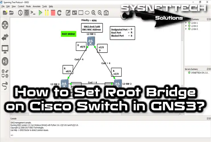
I created the topology for the Priority project in the image below. Do the same for yourself. Then, start by dragging and dropping the L2 switch into the GNS3 workspace. Cable all devices together, as shown in the image. Also, create a more specific project by adding detailed descriptions.

Step 3
So far, I haven’t done anything with Layer 2 Switches. However, I learned the MAC addresses and Priority values of all SWs. I noted them in the project, as shown below.
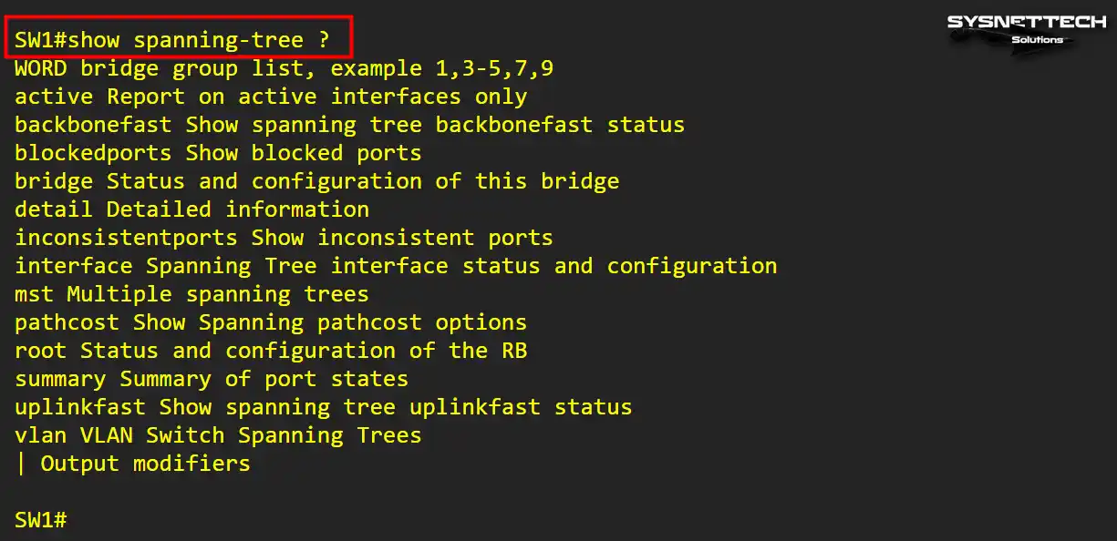
You can find these values for all Switches in your project by showing the spanning-tree command in the CLI.
Now, let’s execute the relevant show command on L2-SW-2. When we check the result in GNS3, you will see that it is the “This bridge is the root,” as shown in the image below.

Step 4
In this project, we will make the selection manually. So, let’s identify the central device in the network. For example, let’s make L2-SW-1 central according to this topology.
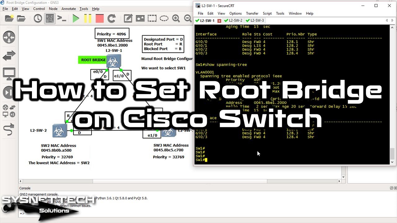
Now open the CLI command prompt of SW-1. Immediately after that, execute the command spanning-tree vlan 1 priority 4096.
SW1# conf t
SW1(config)# spanning-tree vlan 1 priority 4096

Step 5
I changed the Priority for the L2-SW-1 Switch. At this point, other devices on the network will send and receive BPDU packets. As a result, when they agree, SW-1 will become the Core Switch.
If you want to control this process, use the show spanning-tree command in SW-1. This time, you will see that Switch also changes port states, as shown in the result below.

Step 6
After determining the Master Switch, the port states also changed. Thus, you can now see the new states of SW1.

Step 7
Check the L2-SW-2 port status as below. On this device, the Gig0/0 port will be Root. If Gig0/1, it will be Desg, i.e. Designated.

Step 8
Likewise, see L2-SW-3 port statuses. This time, the port connected to SW2, i.e., Gig0/1, will be Altn (Alternate). The Gig0/2 interface going to SW1 will be central.

Step 9
Let’s look at SW-1 again. According to our topology, we can now see that this is Root. In addition, GigabitEthernet0/0 and 0/1 ports are Desg, that is, Designated Port.

Show Commands for Central Switch
| Command | Explanation |
|---|---|
SW1#show spanning-tree | It shows the current spanning tree status of switch SW1. Also, it contains essential information such as bridge ID, role, status, and ports. |
SW2#show spanning-tree | We use it for the same purpose for SW2. In short, it contains similar information to that described for SW1. However, it determines the role of SW2 in the network topology. |
SW3#show spanning-tree | In this command, we get valid information for SW3. Additionally, we find the information disclosed for SW1 and SW2. However, we only learned the current information on SW3 in the network. |
SW1#show spanning-tree detail | We’ll get lots of info about the STP available for device SW1. These details include communication costs between bridges or the status of ports. |
SW1#show spanning-tree bridge | We learn the bridge information of SW1. For example, these are basic information such as ID and the status of ports. |
SW1#show spanning-tree ? | We find its subcommands and options for the show spanning-tree command. |
1) SW1#show spanning-tree

2) SW2#show spanning-tree

3) SW3#show spanning-tree

4) SW1#show spanning-tree detail

5) SW1#show spanning-tree bridge

6) SW1#show spanning-tree ?
How to Set Up Root Bridge Switch ⇒ Video
To help you understand how to select the Root Bridge, we’ve made a helpful video. And if you want to support us, you can subscribe to our YouTube channel. Thanks!
Frequently Asked Questions (FAQ) About Root Switch
- What is Root Bridge?
- How can I find the Root Bridge on my network?
- Where should I place the Bridge Switch on the network?
- Which device takes Priority in Root Switch selection?
Conclusion
As a result, it is easy to change the Priority value of a Layer 2 Switch in a GNS3 network. In this way, we set a device we want as Root. But, if we use STP for our existing devices, this process is automatic. However, sometimes, we need to manually set the central Switch on Cisco devices.
Of course, in this guide, I told you about device selection with Priority. But you can also use the MACs or Costs of the devices if you wish. Thus, you can quickly determine the central point of the entire data flow. As a result, you can create backup routes by providing a reliable environment.
In short, we were able to manually select the Root Bridge with the simulation tool in GNS3. Nevertheless, of course, you should try something other than an actual LAN topology. Just understand the logic or improve yourself for the exams.

Be the first to share your comment