
Cisco sınavlarına hazırlanıyorsanız GNS3 kullanan Router’larda OSPF kurulumu konusunda yardım ister misiniz? Bu anlaşılması kolay yazımızda, Open Shortest Path First anlamına gelen OSPF’den bahsedeceğiz.
GNS3 ile gerçek ağ durumlarını simüle edebilir ve deneyebilirsiniz. Ağlarla çalışan kişiler ve öğrenciler, ağların nasıl çalıştığını anlamak için bu yazılımı çok kullanırlar. Böylece OSPF gibi farklı protokollerde yetkin hale gelebilirler.
Cisco Router Üzerinde OSPF Neden Yapılandırıyoruz?
OSPF, bir ağdaki bilgi için en iyi talimatları gönderen yararlı bir araç gibidir. Bu bir bağlantı durumu yönlendirmesidir. Bu nedenle, bir iç ağ geçidi protokolü (IGP) olduğu için büyük kurumsal ağlarda yaygın olarak kullanılıyorlar.
1. Verimli Yönlendirme
Bu protokol, hiyerarşik bir ağ yapısı kullanan Router’ların bağlantı durumuna göre hesaplamalara bakar. Daha sonra işlerin gitmesi gereken yere giden en hızlı yolu bulur ve bilgiyi bu yol boyunca gönderir.
Ağdaki Yönlendiricilerde veya bağlantı noktalarında bir şeyler ters giderse, OSPF hızla devreye girer ve sorunu düzeltir. Topolojideki değişikliklere hızlı ve verimli bir şekilde uyum sağlar. Bu, ağın iyi çalıştığından emin olarak işletmelerin sorunsuz bir şekilde çalışmaya devam etmesine yardımcı olur.
Ayrıca başkalarına çok hızlı bilgi göndermenin en iyi yollarını anlatır. Bu şekilde ağın tam bir haritasını çıkarır.
2. Ölçeklenebilirlik
Bunu bir Cisco Router’da kullanmanın başka bir iyi yanı daha var; çok fazla büyümeyi kaldırabilir. Bu nedenle onu binlerce cihaza sahip geniş ağlarla iyi çalışacak şekilde tasarladılar. Yani ağınız büyüdükçe, bununla başa çıkmak için kendini değiştirebilir ve organize edebilir. Bu şekilde ağınızın sağlam ve güvenilir kaldığından emin olabilirsiniz.
Ağların büyüdüğü veya çok fazla trafiğe ihtiyaç duyduğu noktalarda büyüyebilmek son derece önemlidir. Basit bir ifadeyle, her şeyi bozmadan kolayca yeni yönlendiriciler ekleyebilirsiniz. Ayrıca mevcut cihazları yeniden yapılandırabilirsiniz.
3. Hata Toleransı
Bu protokol kuralları seti aynı zamanda Cisco cihazlarının sorunları çözmesini de kolaylaştırır. Böylece ağdaki sorunları hızlı bir şekilde bulabilir ve onarabilirsiniz.
Yani bir şeyler ters giderse bilginin yayılma şeklini hızla değiştirir. Basit bir ifadeyle, bağlantı kopsa bile ağın kesintisiz olarak devam etmesini sağlayabilirsiniz.
4. Yük Dengeleme
Bu protokol ayrıca kurulumunuz başka bir iyi şey daha getiriyor: yük dengeleme. Bu, ağ trafiğini farklı yollara yayarak bir yolun aşırı kalabalıklaşmasını önleyeceğiniz anlamına gelir. Böylece yük dengelemeyle ağın iyi çalıştığından ve yönetilebilir olduğundan emin olursunuz.
Bu özelliği çok fazla trafiğe sahip cihazlarda kullandığınızda gerçekten iyi çalışır. Böylece mevcut tüm farklı yolları kullanarak ağ kaynaklarını akıllıca kullanabilirsiniz.
5. Güvenlik
Cisco Router’da OSPF’yi açmak elbette ağı daha güvenli hale getirir. Böylece, cihazlar arasındaki yönlendirme bilgilerinin bütünlüğünü kontrol etmek için kimlik doğrulamayı kullanabilirsiniz. Bu şekilde kodla yalnızca güvendiğiniz cihazlar ağın parçası olabilir.
Basit bir ifadeyle, orada olmaması gereken cihazların ağın bilgi gönderme şekline müdahale etmesini engellersiniz. Bu şekilde kötü şeylerin sisteme girmesini engellemiş olursunuz. Dolayısıyla işletmeler ve gruplar için bu kurallar dizisi hayati öneme sahiptir ve tüm kurulumu güvende tutar.
GNS3 Üzerinde OSPF Routing Etkinleştirme
Bu protokolü bir ağ üzerinde kurduğunuzda, Router’lar birbirleriyle aynı AS (Autonomous System – Otonom Sistem) numarasını kullanarak konuşur. Ancak farklı AS numaralarına sahip farklı gruplardaki cihazlarla da konuşmalarını sağlayabilirsiniz. Temel olarak AS’deki her Yönlendirici tüm ağ düzenlerini bilir. Böylece hedefe ulaşmanın en iyi yolunu hızla bulabilirler.
Ayrıca bu, EIGRP protokolüne benzer. Ancak en büyük fark, EIGRP’nin yalnızca Cisco cihazlarıyla çalışmasıdır. Dolayısıyla bunu kullanmak mükemmel çünkü hem Cisco hem de diğer markaların cihazlarıyla çalışıyor.
Başlamadan Önce
GNS3 ağ yazılımında OSPF işlemlerini yapmaya başlamadan önce şunları bilmelisiniz:
- Router ID: Bu, ağdaki her cihaza onları birbirinden ayırabilmemiz için verilen benzersiz bir numaradır.
- Area ID: Bu, ağdaki cihazlar için bir grup kimliği gibidir. Bunları mantıksal olarak düzenlemeye ve gruplandırmaya yardımcı olur.
- Network ID: Her ağa atanan benzersiz bir grubu ifade eder.
- Interface: Bu, Yönlendirici üzerinde bir ağa bağlanan fiziksel veya sanal bağlantıdır.
GNS3’te Yeni OSPF Topolojisi Oluşturma
Öncelikle GNS3 üzerinde OSPF için yeni bir topoloji yapmalısınız. Bunu tamamladıktan sonra bu mükemmel yönlendirme planını kullanmaya başlayabilirsiniz.
İhtiyacınız olan tek şey GNS3, iki adet Router, Switch ve VMware sanal makinesidir. Cloud PC‘yi kullanarak VMware Workstation üzerinde çalışan VM’lerinizi dahil edebilirsiniz. Bu, protokolün nasıl çalıştığını daha gelişmiş bir şekilde öğrenmenize yardımcı olur.
Adım 1
Şimdi link state protokolü için GNS3 programını başlatınız ve yeni bir proje oluşturunuz.

Adım 2
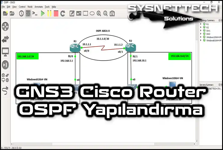
Bizim yaptığımız gibi aşağıdaki resimdeki gibi bir ağ kurulumu yapın. Ayrıca farklı parçalara ad veya açıklama vermek de iyi bir fikirdir. Bu şekilde ağı nasıl kurduğunuzu anlamak daha kolay olacaktır.

Adım 3
VMware programınızda iki adet sanal bilgisayar oluşturun. Daha sonra sanal ağ ayarlarını doğru yaptığınızdan emin olun. Bu kılavuzda Windows 8.1 ve 10 kullanıyoruz. Ancak isterseniz daha yeni veya daha eski olanları da kullanabilirsiniz.
Son olarak aşağıdaki görüntüdeki gibi Windows 8.1 VM ayarlarında VMnet1 seçeneğini seçiniz.

Adım 4
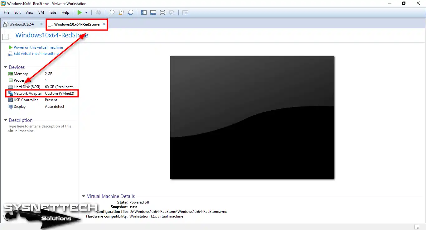
Aynı şekilde Windows 10 sanal makine ağ kartı ayarlarına da göz atmalısınız. Bu nedenle konuk makinenin ekranında VMnet2’yi seçtiğinizden emin olun.
Adım 5
VMware Virtual Network Editor’da VMnet ayarlarını kontrol etmelisiniz. Böylece Win8 için VMnet1’i, Win10 için VMnet2’yi ayarlayın.

Adım 6
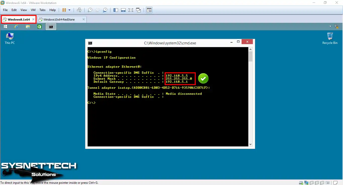
Daha sonra VMware aracında sanal bilgisayarları başlatın. Ve karar verdiğiniz alt ağa göre TCP/IP ayarlarını yapın. Örneğin aşağıdaki resimde Win8 için IP detaylarını inceleyebilirsiniz.
Adım 7
İş İstasyonundaki sanal Win10 bilgisayarının TCP/IP ayarlarını şu şekilde yapın:

Cisco Router’ların Bağlantı Noktalarını Yapılandırma
Şu ana kadar sadece ağı düzenlediniz ve TCP/IP ayarlarını yaptınız. Şimdi bir sonraki adım, çalışma alanına koyduğunuz Cisco Router’larda OSPF yönlendirmesinin çalışmasını sağlamaktır.
Adım 1
Şimdi Cisco R1 üzerinde FastEthernet ve Seri bağlantılarını kurun. Bunun için R1 CLI ekranındaki bu komutları takip edin.
Ayrıca Cisco R1’de yaptığınız değişiklikleri de tekrar kontrol etmek istiyorsunuz. Bunu yapmak için CLI’ye “show ip interface brief” yazarak durumu görün.
R1#conf t
R1(config)#interface fastethernet 0/0
R1(config-if)#ip address 192.168.5.1 255.255.255.0
R1(config-if)#no shutdown
R1(config-if)#exit
R1(config)#interface serial 0/0
R1(config-if)#ip address 10.1.1.1 255.255.255.252
R1(config-if)#no shutdown
R1(config-if)#end
Adım 2
Benzer şekilde Cisco R2 üzerindeki FastEthernet ve Serial kısımlarını da plana göre düzenleyiniz. Bundan sonra, daha önce kullandığımız komutun aynısını kullanarak portların durumuna bakın.
R2#conf t
R2(config)#interface fastethernet 0/1
R2(config-if)#ip address 192.168.10.1 255.255.255.0
R2(config-if)#no shutdown
R2(config-if)#exit
R2(config)#interface serial 0/1
R2(config-if)#ip address 10.1.1.2 255.255.255.252
R2(config-if)#no shutdown
R2(config-if)#end
Adım 3
Şu ana kadar Router’lar üzerinde FastEthernet ve Serial kısımlarını kurdunuz. Ancak henüz ağ cihazlarında herhangi bir yönlendirme planını etkinleştirmediniz. Bunu daha net görebilmek için VM’ler arasındaki bağlantıyı kontrol edin.
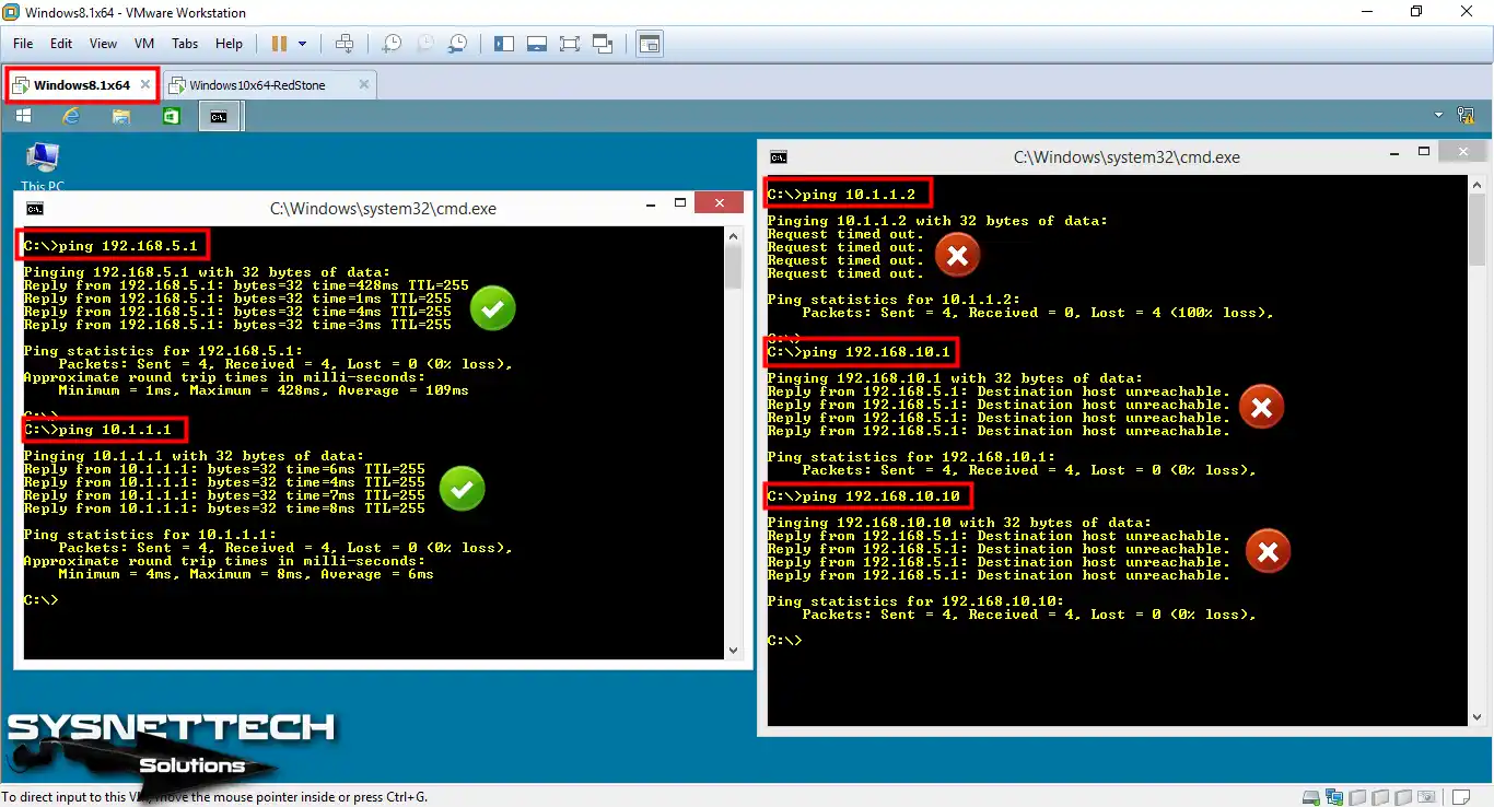
Şimdi, bağlı olup olmadıklarını görmek için Win8.1 makinesinden R1’e ping atmayı deneyin. Ardından Win8.1’in R2’ye de ulaşıp ulaşamadığını kontrol edin.
Adım 4
Aynı işlemleri Win10 makinede de yapın. Her iki ping testinde de karşı ağın başarısız olacağını göreceksiniz. Özetle PC’ler yalnızca doğrudan bağlantıya sahip oldukları yönlendiricilerin bağlantı noktalarına ping atmaya başlayabilirler.
OSPF henüz kurulumda açık olmadığından diğer ağa ping atamıyorlar!

Cisco Router OSPF Protokolünü Etkinleştirme
Artık topolojide Router’larda routing özelliğini açmanız gerekmektedir. Bu sayede Win8 ve Win10 makineleri birbirleriyle konuşabilir.
Adım 1
Open Shortest Path First etkinleştirmek için Cisco Router R1 üzerinde komut bölümünü açın. Daha sonra komut ekranına bu komutları tek tek yazın.
R1#conf t
R1(config)#router ospf 10
R1(config-router)#network 192.168.5.0 0.0.0.255 area 0
R1(config-router)#network 10.1.1.0 0.0.0.3 area 0
R1(config-router)#end
Adım 2
Elbette bunu diğer Router R2’de de etkinleştirmeniz gerekir. Bunu atlarsanız cihazlar birbirlerine topoloji bilgilerini söyleyemez.
R2#conf t
R2(config)#router ospf 10
R2(config-router)#network 192.168.10.0 0.0.0.255 area 0
R2(config-router)#network 10.1.1.0 0.0.0.3 area 0
R2(config-router)#
R2(config-router)#end
NOT: R2’de etkinleştirdiğinizde ekranda bir mesaj göreceksiniz. Şöyle devam ediyor: “*Mar 1 00:18:09.227: %O-S-P-F-5-ADJCHG: Process 10, Nbr 192.168.5.1 on Serial0/1 from LOADING to FULL, Loading Done.” Bu size R1’in 192.168.5.1 adresli seri kısmının R2 ile birlikte çalışmaya başladığını bildirir.
Adım 3
GNS3 ile Router’larda OSPF işini yaptığından emin olmanız gerekmektedir. Bu yüzden hem R1 hem de R2’ye “show ip route” yazarak rota bilgisine bakın.

PC’lerin Ağ Bağlantısını Test Etme
Adım 1
Artık yönlendiriciler çalışma alanında topoloji bilgilerini paylaşıyor. Rota bilgisi iyi görünüyorsa VMware makinelerinden ping atmayı deneyin.
Şimdi diğer Win8 VM’ye ping atın ve işlemi kontrol edin.

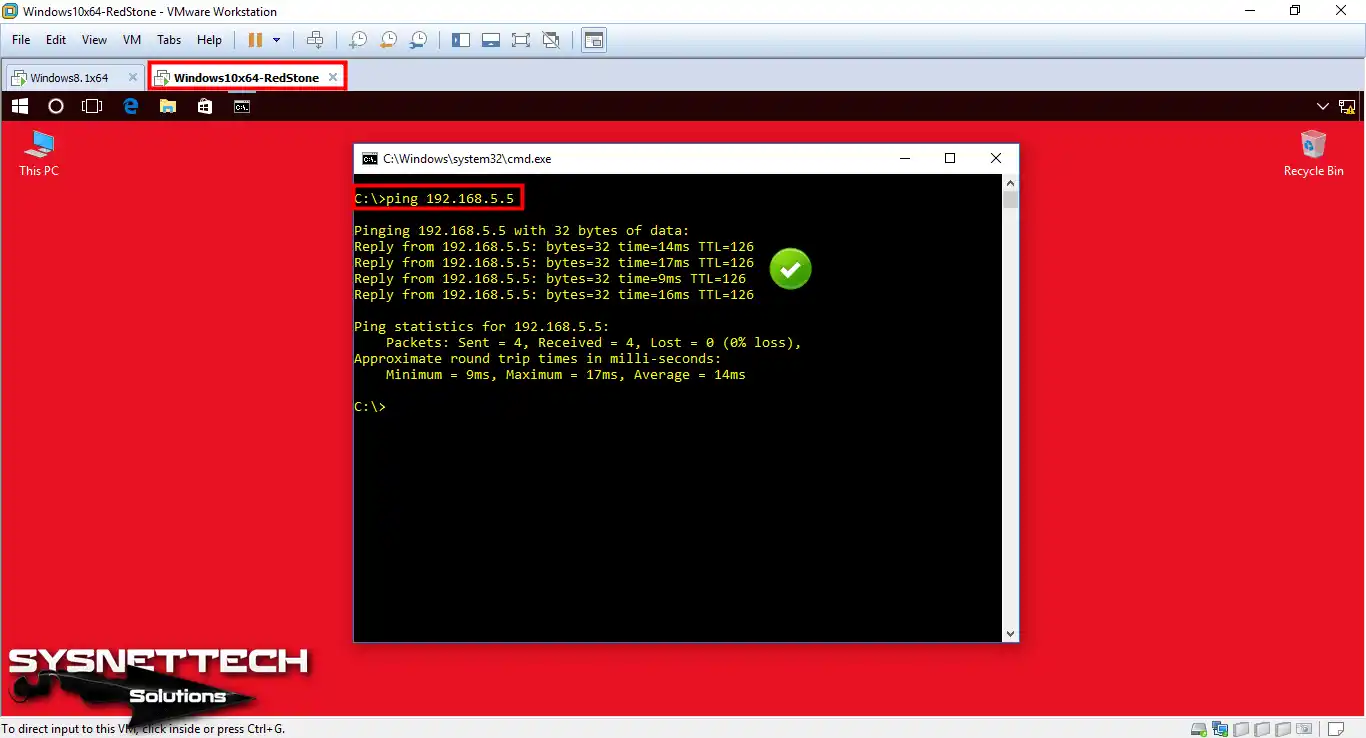
Adım 2
Aşağıdaki görüntüdeki gibi Win10 PC’den karşı ağa ping işlemi başarılı oluyor. Böylece 5.0/24 ağına sorunsuz bir şekilde erişebileceksiniz.
GNS3’te OSPF Show İnceleme
Open Shortest Path First kurulumunu sorunsuz bir şekilde tamamladık. Şimdi Router’lardaki show komutlarına göz atalım.
Adım 1
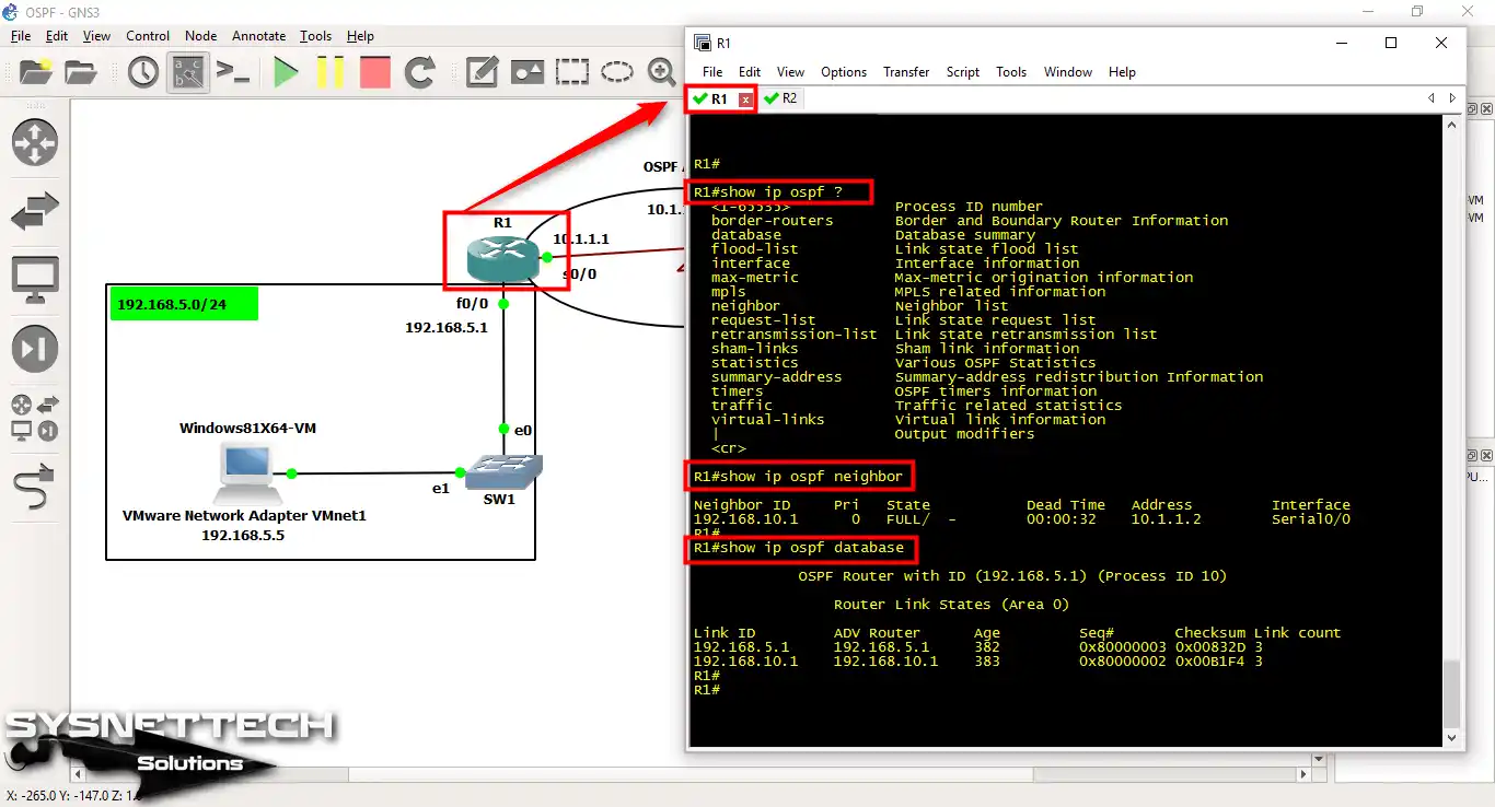
Cisco R1’in CLI ekranında şu show komutlarını kullanın:
- show ip ospf neighbor: Bu komut size komşular ve onların durumları hakkında bilgi verir.
- show ip ospf database: Bu komut size yönlendiricilerin durumu, bağlantıları ve diğer kurulum ayrıntıları hakkında bilgi verir.
Adım 2
Yukarıdaki komutları R2 üzerinde çalıştırın ve inceleyin.

Adım 3
Yönlendirme özelliğini kontrol etmek için “debug ip ospf hello” kullanabilirsiniz. Yani bu komut “hello” mesajlarıyla ilgili ekstra ayrıntıları görmenizi sağlar.
Hello mesajı, komşu cihazlar arasında iyi ilişkiler kurulmasını sağlar. Kısaca bu mesajları Multicast adresini (224.0.0.5) kullanarak gönderir.
Şimdi R1 cihazında “debug ip ospf hello” komutunu çalıştırın ve sonuçları görün.

Adım 4
Aynı komutu R2’ye yazarak merhaba mesajlarına göz atabilirsiniz.

Adım 5
Cisco Router R1 ve R2 üzerinde OSPF için tüm ayarları yaptınız. Şimdi ayarları daha kısaca kontrol etmeniz gerekiyor. Bunu yapmanın en temel yolu “show running-config” komutunu kullanmaktır.
Yani R1 ve R2’de çalışan yapılandırma ayarları şöyledir:

Wireshark ile OSPF Doğrulama
Bu yönlendirmenin çalıştığından emin olmanın başka bir yolu da Wireshark kullanmaktır. Bu program ile sadece rota planlarını değil aynı zamanda geçen tüm verileri de kontrol edebilirsiniz.
Adım 1
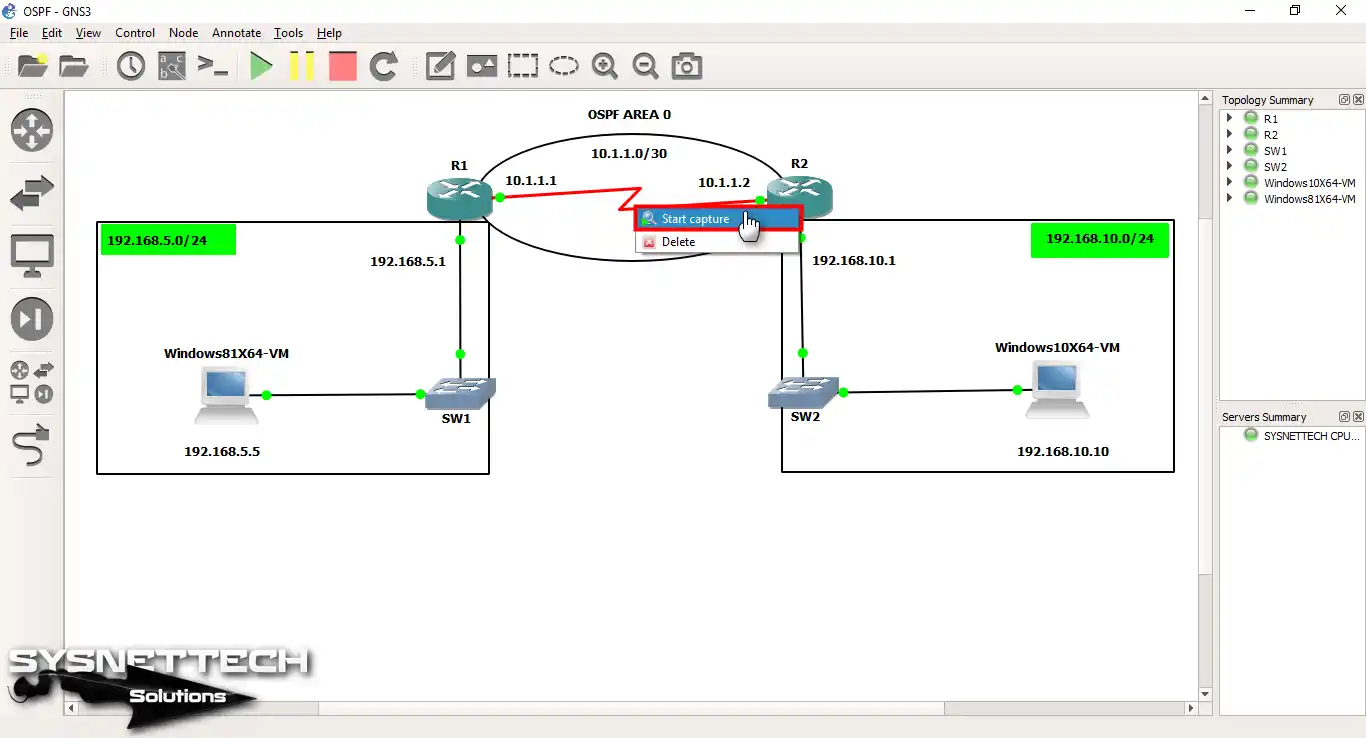
Şimdi sağ tuşa basın ve Router’lar arasındaki seri kablo üzerinde “Start Capture” seçeneğini seçin.
Adım 2
Paketleri yakalayacağınız bir pencere açacaksınız. “File name” yazan kısma bakın. Daha sonra analize başlamak için OK’a tıklayın.

Adım 3
Arayüzü seçtiğinizde Wireshark açılır. Şimdi topolojide Router’lar arasında hareket eden Hello paketlerine bir göz atın.
Multicast (224.0.0.5) kullanarak hello mesajları gönderip göndermediğini kontrol ederek çalıştığından emin olabilirsiniz.

GNS3 ile OSPF Eğitimi İçin YouTube Videomuz
Bu kurulum adımlarını daha kolay anlamanıza yardımcı olmak için YouTube’da bir eğitim videosu hazırladık. Aşağıdaki videoya göz atacağınızı ve Cisco OSPF’yi kurmanın daha kolay bir yolunu bulmamıza yardımcı olacağınızı umuyoruz.
Sık Sorulan Sorular (SSS / FAQ)
- Cisco Router’ımın OSPF’yi destekleyip desteklemediğini nasıl kontrol ederim?
- OSPF’yi yapılandırmanın önkoşulları nelerdir?
- OSPF sorunları nasıl giderilir?
Sonuç
Sonuç olarak OSPF, kuruluşların ağlarını iyi bir şekilde yönetmelerine yardımcı olur. Akıllı yönlendirme sağladığı için iç ağlar için iyi bir araçtır. Ayrıca ağ büyüdükçe büyür, sorunlarla ilgilenir, ağ trafiğini dağıtır ve işleri güvende tutar. Ayrıca, çok sayıda cihazın bulunduğu geniş ağların bakımı için mükemmeldir.
Özetlemek gerekirse bu kılavuzdaki kolay adımları takip ederek GNS3 kullanarak Cisco Router’ınıza OSPF kurulumu yapabilirsiniz. Bu sayede ağınızı bir profesyonel gibi yönetebilir ve Cisco sınavlarına hazırlanabilirsiniz.

İlk yorumu sen paylaş