OSPF (Open Shortest Path First) is a Link-State routing protocol that belongs to the Dynamic Routing class.
How to Configure OSPF Routing on Cisco Router with Packet Tracer
OSPF is a routing protocol used in WAN or business networks. This routing protocol maps the entire network using the SPF algorithm and provides a fast convergence as a result of a failure on a Router on the network. Another route is assigned to the networks connected to the failed Router and the network is maintained.
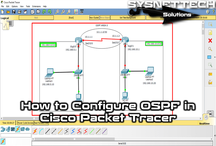
In this article, we will enable the OSPF routing protocol on Routers in two different segments in Packet Tracer.
To configure the OSPF protocol, follow the steps below.
Step 1
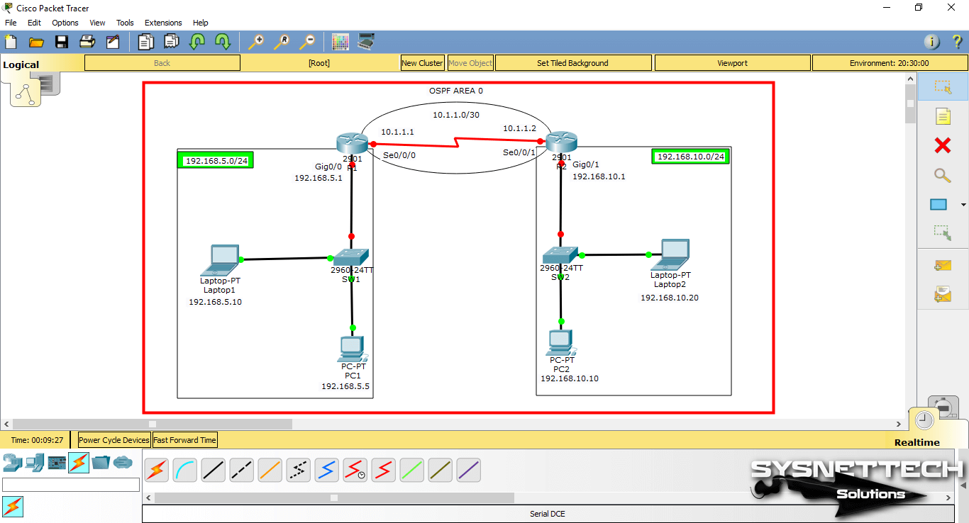
Open Packet Tracer and create the topology as shown in the image below. Also, add comments to the workspace by defining IP address blocks, assigning IP addresses to computers.
Step 2
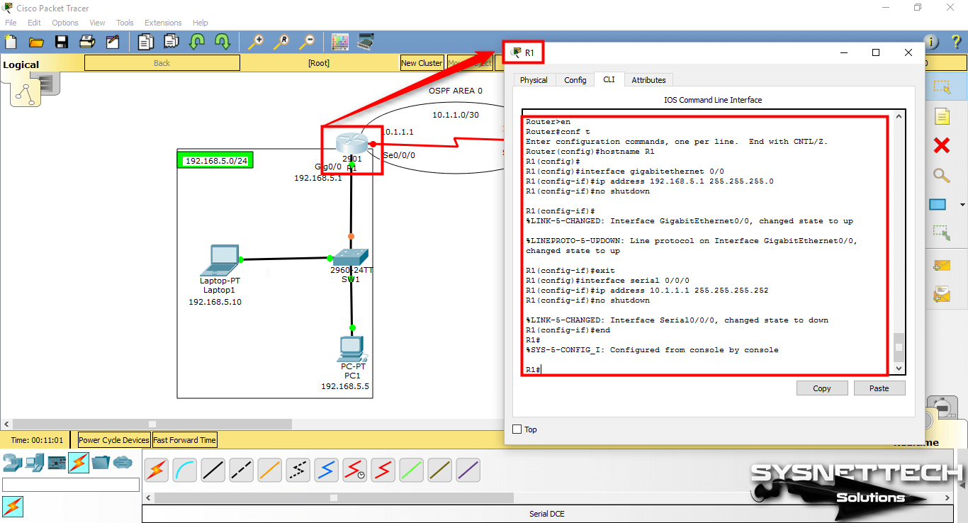
Open the Cisco Router R1 CLI command prompt and configure the GigabitEthernet0/0 and Serial0/0/0 interfaces according to the IP blocks you specify.
Router#conf t
Enter configuration commands, one per line. End with CNTL/Z.
Router(config)#hostname R1
R1(config)#
R1(config)#interface gigabitethernet 0/0
R1(config-if)#ip address 192.168.5.1 255.255.255.0
R1(config-if)#no shutdown
R1(config-if)#
%LINK-5-CHANGED: Interface GigabitEthernet0/0, changed state to up
%LINEPROTO-5-UPDOWN: Line protocol on Interface GigabitEthernet0/0, changed state to up
R1(config-if)#exit
R1(config)#interface serial 0/0/0
R1(config-if)#ip address 10.1.1.1 255.255.255.252
R1(config-if)#no shutdown
R1(config-if)#end
R1#
Step 3
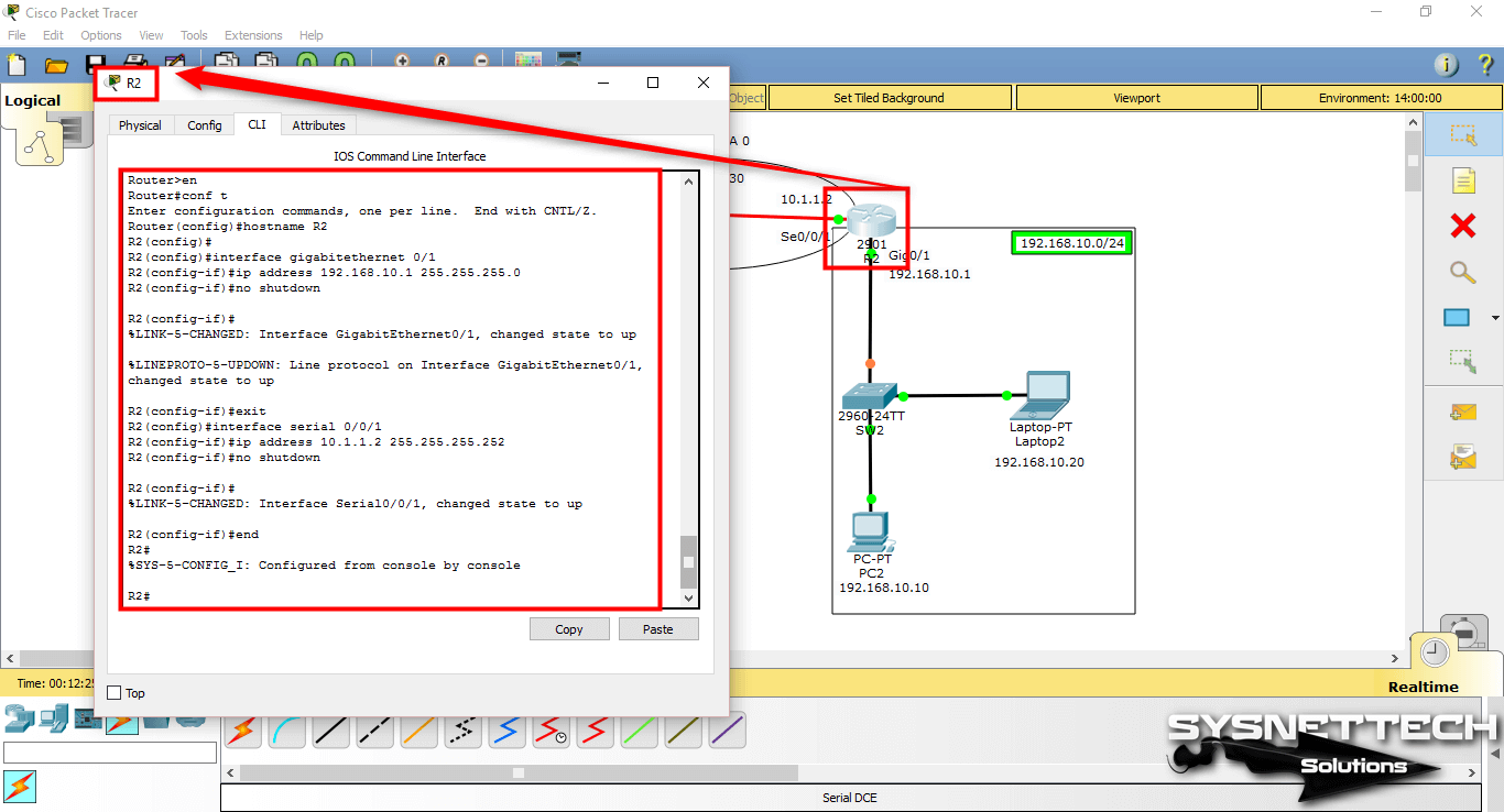
Configure the interfaces of Cisco Router R2 in the same way.
Router#conf t
Enter configuration commands, one per line. End with CNTL/Z.
Router(config)#hostname R2
R2(config)#
R2(config)#interface gigabitethernet 0/1
R2(config-if)#ip address 192.168.10.1 255.255.255.0
R2(config-if)#no shutdown
R2(config-if)#
%LINK-5-CHANGED: Interface GigabitEthernet0/1, changed state to up
%LINEPROTO-5-UPDOWN: Line protocol on Interface GigabitEthernet0/1, changed state to up
R2(config-if)#exit
R2(config)#interface serial 0/0/1
R2(config-if)#ip address 10.1.1.2 255.255.255.252
R2(config-if)#no shutdown
R2(config-if)#
%LINK-5-CHANGED: Interface Serial0/0/1, changed state to up
R2#
Step 4
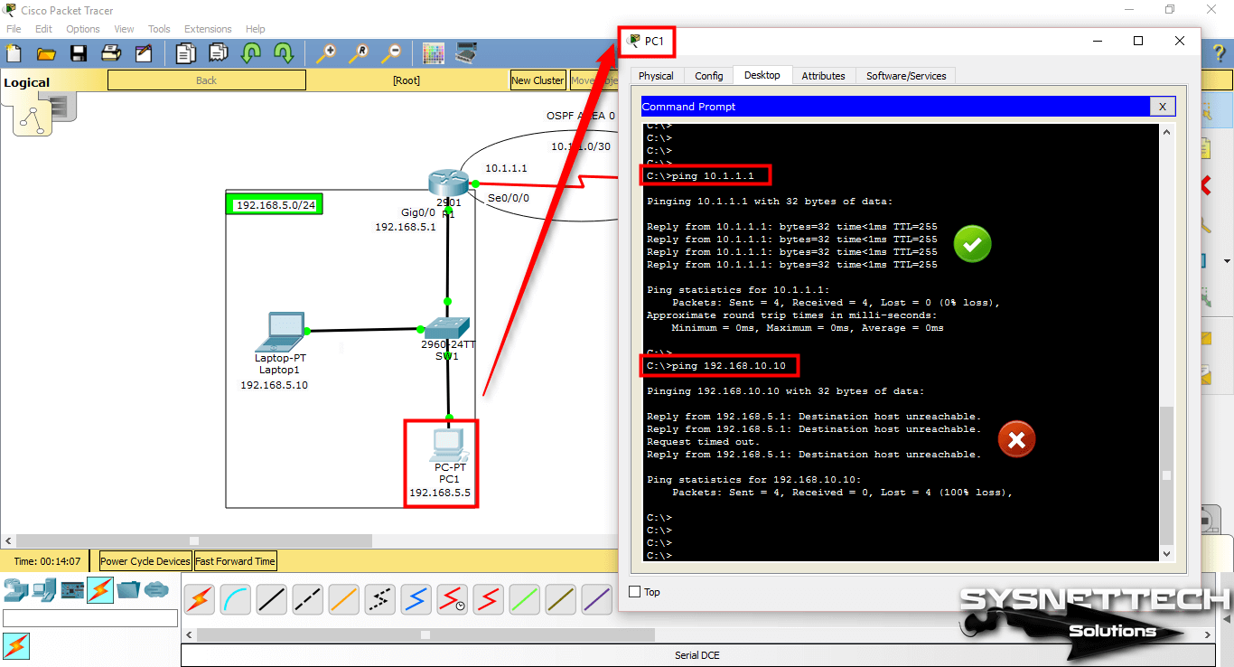
Before enabling the routing protocol, Ping the segments to test the network connection.
Ping through R1 to Serial0/0/0 interface of R1 via PC1 will succeed, but ping to PC2 with IP address 192.168.10.10 in the other segment will fail.
Step 5
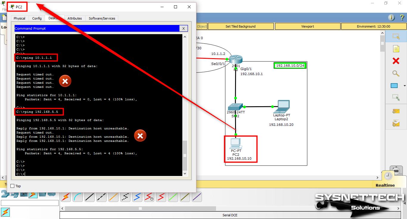
Ping from PC2 to R1’s Serial0/0/0 interface and PC1.
The reason for the ping error is that no routing protocol is configured on the routers.
Step 6
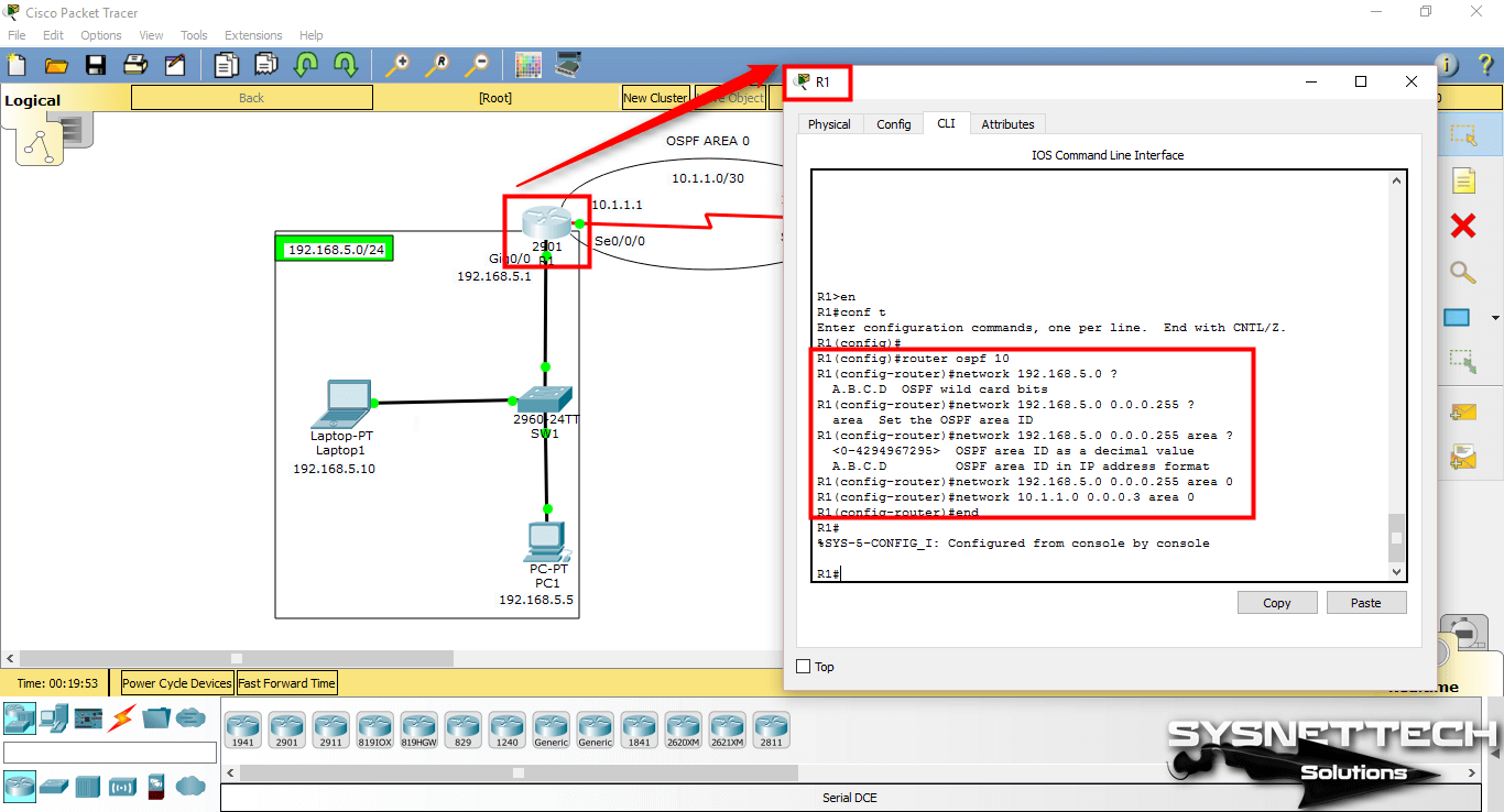
Use the following commands to enable OSPF Routing on Cisco Routers to communicate the two segments to each other.
R1#conf t
Enter configuration commands, one per line. End with CNTL/Z.
R1(config)#
R1(config)#router ospf 10
R1(config-router)#network 192.168.5.0 ?
A.B.C.D OSPF wild card bits
R1(config-router)#network 192.168.5.0 0.0.0.255 ?
area Set the OSPF area ID
R1(config-router)#network 192.168.5.0 0.0.0.255 area ?
OSPF area ID as a decimal value
A.B.C.D OSPF area ID in IP address format
R1(config-router)#network 192.168.5.0 0.0.0.255 area 0
R1(config-router)#network 10.1.1.0 0.0.0.3 area 0
R1(config-router)#end
R1#
Step 7
In the same way, after enabling OSPF Routing on Router R2, you can see that a neighbor is established between R1 and R2.
NOTE: Wildcard mask is used when adding network addresses for OSPF.
R2#conf t
Enter configuration commands, one per line. End with CNTL/Z.
R2(config)#
R2(config)#router ospf 10
R2(config-router)#network 10.1.1.0 0.0.0.3 area 0
R2(config-router)#network 192.168.
00:16:00: %OSPF-5-ADJCHG: Process 10, Nbr 192.168.5.1 on Serial0/0/1 from LOADING to FULL, Loading Done
^
% Invalid input detected at '^' marker.
R2(config-router)#network 192.168.10.0 0.0.0.255 area 0
R2(config-router)#end
R2#

Step 8
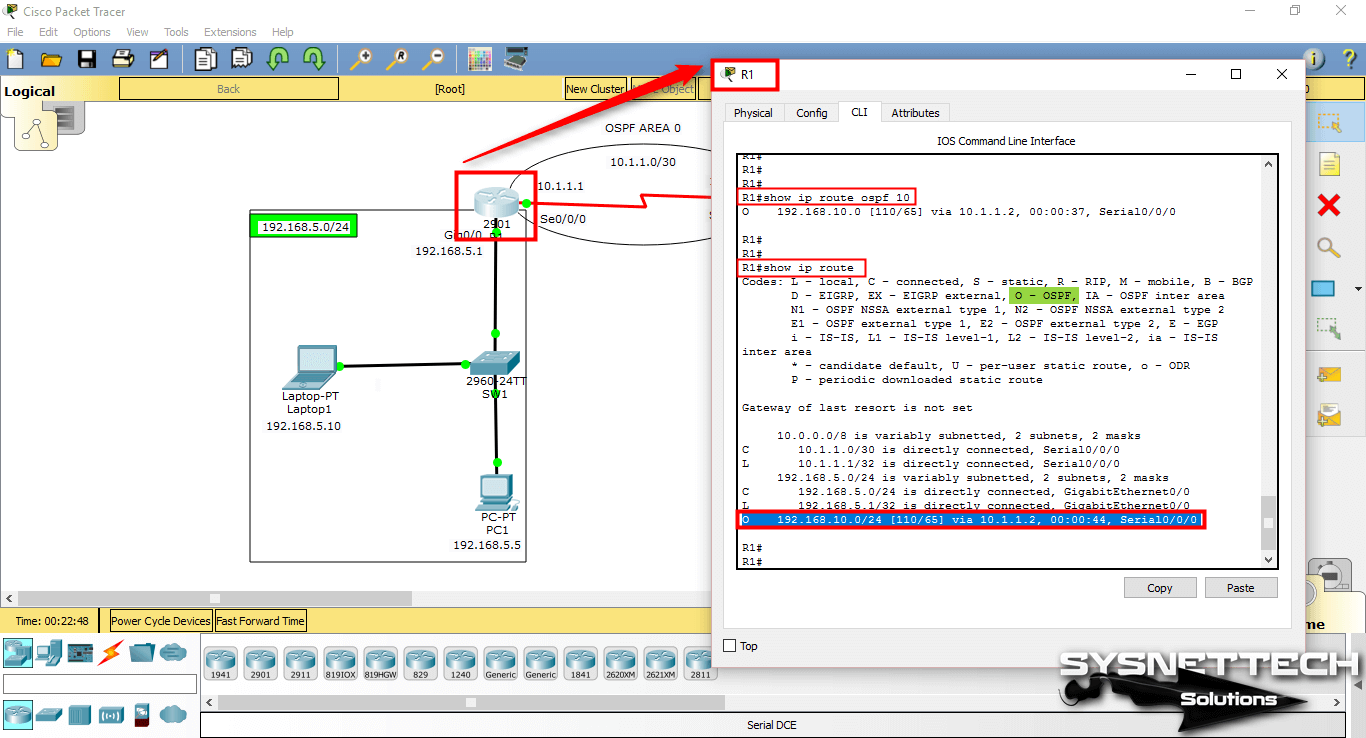
Execute the show ip route ospf 10 command on Router R1 and examine the routing table.
R1#show ip route ospf 10
O 192.168.10.0 via 10.1.1.2, 00:00:37, Serial0/0/0
In addition, execute the show ip route command to see that the Routing protocol is identified by the letter O.
R1#
R1#show ip route
Codes: L - local, C - connected, S - static, R - RIP, M - mobile, B - BGP
D - EIGRP, EX - EIGRP external, O - OSPF, IA - OSPF inter area
N1 - OSPF NSSA external type 1, N2 - OSPF NSSA external type 2
E1 - OSPF external type 1, E2 - OSPF external type 2, E - EGP
i - IS-IS, L1 - IS-IS level-1, L2 - IS-IS level-2, ia - IS-IS inter area
* - candidate default, U - per-user static route, o - ODR
P - periodic downloaded static route
Gateway of last resort is not set
10.0.0.0/8 is variably subnetted, 2 subnets, 2 masks
C 10.1.1.0/30 is directly connected, Serial0/0/0
L 10.1.1.1/32 is directly connected, Serial0/0/0
192.168.5.0/24 is variably subnetted, 2 subnets, 2 masks
C 192.168.5.0/24 is directly connected, GigabitEthernet0/0
L 192.168.5.1/32 is directly connected, GigabitEthernet0/0
O 192.168.10.0/24 via 10.1.1.2, 00:00:44, Serial0/0/0
R1#
Step 9
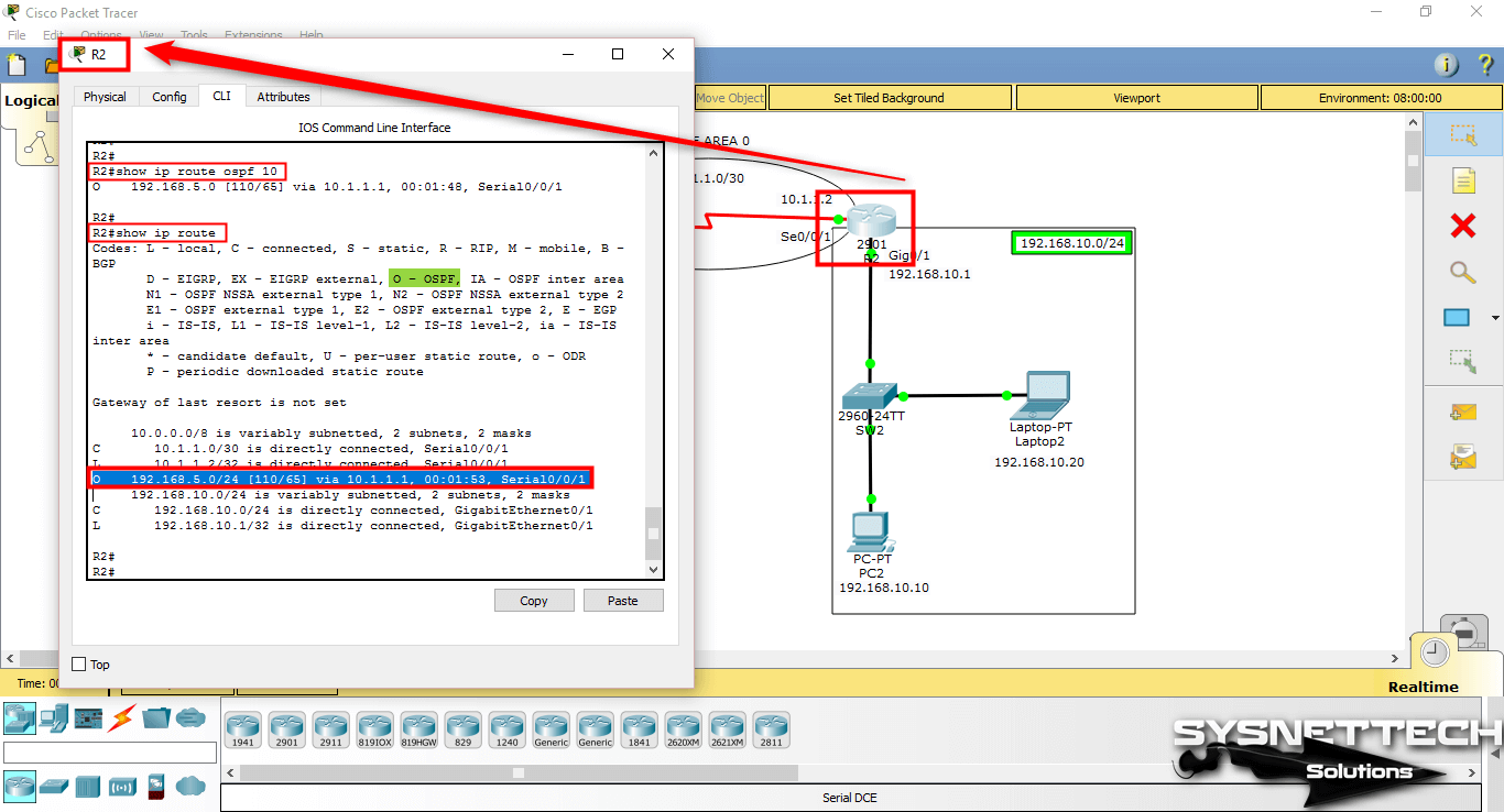
On R2, execute the command show ip route ospf 10 and show ip route.
R2#show ip route ospf 10
O 192.168.5.0 via 10.1.1.1, 00:01:48, Serial0/0/1
Show ip route command output;
R2#show ip route
Codes: L - local, C - connected, S - static, R - RIP, M - mobile, B - BGP
D - EIGRP, EX - EIGRP external, O - OSPF, IA - OSPF inter area
N1 - OSPF NSSA external type 1, N2 - OSPF NSSA external type 2
E1 - OSPF external type 1, E2 - OSPF external type 2, E - EGP
i - IS-IS, L1 - IS-IS level-1, L2 - IS-IS level-2, ia - IS-IS inter area
* - candidate default, U - per-user static route, o - ODR
P - periodic downloaded static route
Gateway of last resort is not set
10.0.0.0/8 is variably subnetted, 2 subnets, 2 masks
C 10.1.1.0/30 is directly connected, Serial0/0/1
L 10.1.1.2/32 is directly connected, Serial0/0/1
O 192.168.5.0/24 via 10.1.1.1, 00:01:53, Serial0/0/1
192.168.10.0/24 is variably subnetted, 2 subnets, 2 masks
C 192.168.10.0/24 is directly connected, GigabitEthernet0/1
L 192.168.10.1/32 is directly connected, GigabitEthernet0/1
R2#
Step 10
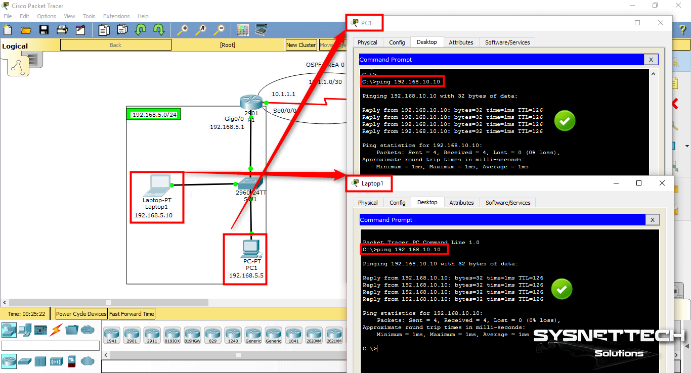
After configuring OSPF routing on the routers, Ping the computers again to check the network connection.
Pinging from 192.168.5.0/24 to 192.168.10.0/24 will succeed as follows.
Step 11
Similarly, Ping from the other segment will be successful as follows.

Step 12
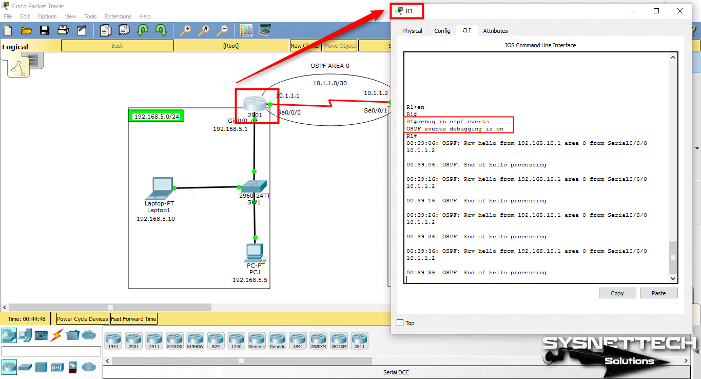
You can use debug ip ospf events in privileged mode to verify the routing protocol.
Step 13
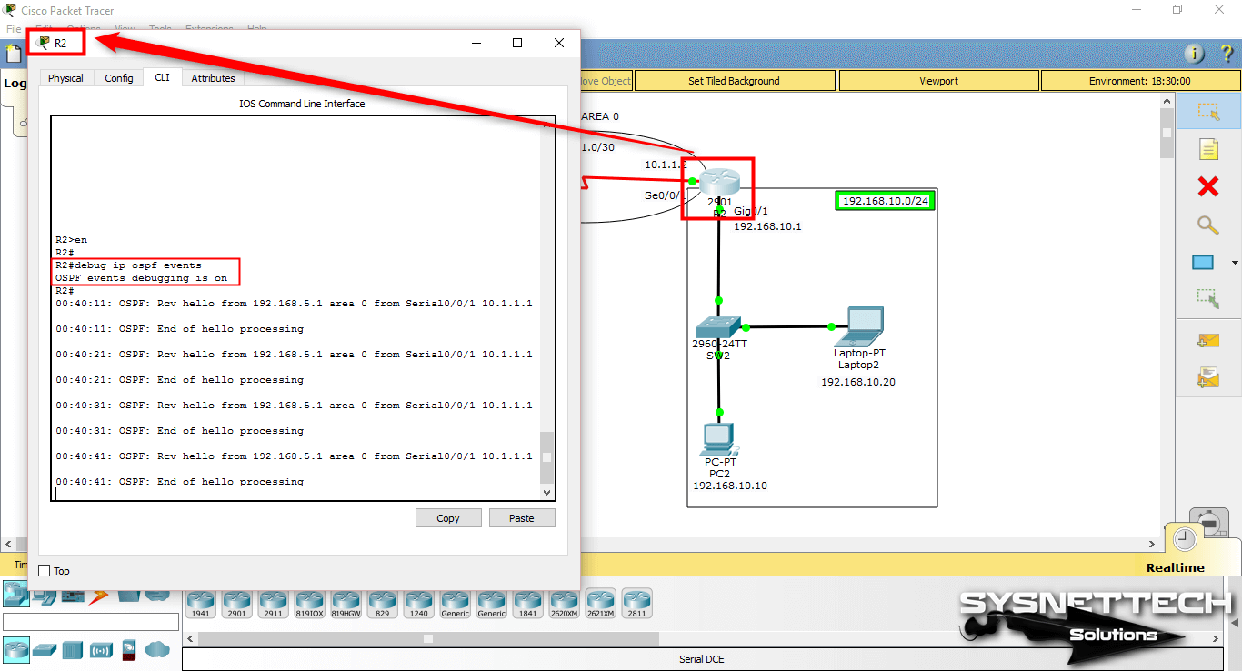
Hello packets are sent to maintain neighborhood relationships between the two Routers.
Show Commands
R1#show ip ospf database
OSPF Router with ID (192.168.5.1) (Process ID 10)
Router Link States (Area 0)
Link ID ADV Router Age Seq# Checksum Link count
192.168.5.1 192.168.5.1 858 0x80000003 0x0002d9 3
192.168.10.1 192.168.10.1 848 0x80000003 0x00349c 3
R1#
R1#show ip ospf interface
GigabitEthernet0/0 is up, line protocol is up
Internet address is 192.168.5.1/24, Area 0
Process ID 10, Router ID 192.168.5.1, Network Type BROADCAST, Cost: 1
Transmit Delay is 1 sec, State DR, Priority 1
Designated Router (ID) 192.168.5.1, Interface address 192.168.5.1
No backup designated router on this network
Timer intervals configured, Hello 10, Dead 40, Wait 40, Retransmit 5
Hello due in 00:00:02
Index 1/1, flood queue length 0
Next 0x0(0)/0x0(0)
Last flood scan length is 1, maximum is 1
Last flood scan time is 0 msec, maximum is 0 msec
Neighbor Count is 0, Adjacent neighbor count is 0
Suppress hello for 0 neighbor(s)
Serial0/0/0 is up, line protocol is up
Internet address is 10.1.1.1/30, Area 0
Process ID 10, Router ID 192.168.5.1, Network Type POINT-TO-POINT, Cost: 64
Transmit Delay is 1 sec, State POINT-TO-POINT, Priority 0
No designated router on this network
No backup designated router on this network
Timer intervals configured, Hello 10, Dead 40, Wait 40, Retransmit 5
Hello due in 00:00:01
Index 2/2, flood queue length 0
Next 0x0(0)/0x0(0)
Last flood scan length is 1, maximum is 1
Last flood scan time is 0 msec, maximum is 0 msec
Neighbor Count is 1 , Adjacent neighbor count is 1
Adjacent with neighbor 192.168.10.1
Suppress hello for 0 neighbor(s)
R1#
R1#show ip ospf database router
OSPF Router with ID (192.168.5.1) (Process ID 10)
Router Link States (Area 0)
LS age: 912
Options: (No TOS-capability, DC)
LS Type: Router Links
Link State ID: 192.168.5.1
Advertising Router: 192.168.5.1
LS Seq Number: 80000003
Checksum: 0x02d9
Length: 60
Number of Links: 3
Link connected to: a Stub Network
(Link ID) Network/subnet number: 192.168.5.0
(Link Data) Network Mask: 255.255.255.0
Number of TOS metrics: 0
TOS 0 Metrics: 1
Link connected to: another Router (point-to-point)
(Link ID) Neighboring Router ID: 192.168.10.1
(Link Data) Router Interface address: 10.1.1.1
Number of TOS metrics: 0
TOS 0 Metrics: 64
Link connected to: a Stub Network
(Link ID) Network/subnet number: 10.1.1.0
(Link Data) Network Mask: 255.255.255.252
Number of TOS metrics: 0
TOS 0 Metrics: 64
LS age: 902
Options: (No TOS-capability, DC)
LS Type: Router Links
Link State ID: 192.168.10.1
Advertising Router: 192.168.10.1
LS Seq Number: 80000003
Checksum: 0x349c
Length: 60
Number of Links: 3
Link connected to: another Router (point-to-point)
(Link ID) Neighboring Router ID: 192.168.5.1
(Link Data) Router Interface address: 10.1.1.2
Number of TOS metrics: 0
TOS 0 Metrics: 64
Link connected to: a Stub Network
(Link ID) Network/subnet number: 10.1.1.0
(Link Data) Network Mask: 255.255.255.252
Number of TOS metrics: 0
TOS 0 Metrics: 64
Link connected to: a Stub Network
(Link ID) Network/subnet number: 192.168.10.0
(Link Data) Network Mask: 255.255.255.0
Number of TOS metrics: 0
TOS 0 Metrics: 1
R1#
R1#show ip ospf 10
Routing Process "ospf 10" with ID 192.168.5.1
Supports only single TOS(TOS0) routes
Supports opaque LSA
SPF schedule delay 5 secs, Hold time between two SPFs 10 secs
Minimum LSA interval 5 secs. Minimum LSA arrival 1 secs
Number of external LSA 0. Checksum Sum 0x000000
Number of opaque AS LSA 0. Checksum Sum 0x000000
Number of DCbitless external and opaque AS LSA 0
Number of DoNotAge external and opaque AS LSA 0
Number of areas in this router is 1. 1 normal 0 stub 0 nssa
External flood list length 0
Area BACKBONE(0)
Number of interfaces in this area is 2
Area has no authentication
SPF algorithm executed 4 times
Area ranges are
Number of LSA 2. Checksum Sum 0x003775
Number of opaque link LSA 0. Checksum Sum 0x000000
Number of DCbitless LSA 0
Number of indication LSA 0
Number of DoNotAge LSA 0
Flood list length 0
R1#
R1#show running-config
Building configuration...
Current configuration : 880 bytes
!
version 15.1
no service timestamps log datetime msec
no service timestamps debug datetime msec
no service password-encryption
!
hostname R1
!
no ip cef
no ipv6 cef
!
license udi pid CISCO2901/K9 sn FTX1524W14I
!
spanning-tree mode pvst
!
interface GigabitEthernet0/0
ip address 192.168.5.1 255.255.255.0
duplex auto
speed auto
!
interface GigabitEthernet0/1
no ip address
duplex auto
speed auto
shutdown
!
interface Serial0/0/0
ip address 10.1.1.1 255.255.255.252
clock rate 2000000
!
interface Serial0/0/1
no ip address
clock rate 2000000
shutdown
!
interface Vlan1
no ip address
shutdown
!
router ospf 10
log-adjacency-changes
network 192.168.5.0 0.0.0.255 area 0
network 10.1.1.0 0.0.0.3 area 0
!
ip classless
!
ip flow-export version 9
!
line con 0
!
line aux 0
!
line vty 0 4
login
!
end
R1#
R1#debug ip ospf events
OSPF events debugging is on
R1#
00:39:06: OSPF: Rcv hello from 192.168.10.1 area 0 from Serial0/0/0 10.1.1.2
00:39:06: OSPF: End of hello processing
00:39:16: OSPF: Rcv hello from 192.168.10.1 area 0 from Serial0/0/0 10.1.1.2
00:39:16: OSPF: End of hello processing
00:39:26: OSPF: Rcv hello from 192.168.10.1 area 0 from Serial0/0/0 10.1.1.2
00:39:26: OSPF: End of hello processing
00:39:36: OSPF: Rcv hello from 192.168.10.1 area 0 from Serial0/0/0 10.1.1.2
00:39:36: OSPF: End of hello processing
R2#show ip ospf database
OSPF Router with ID (192.168.10.1) (Process ID 10)
Router Link States (Area 0)
Link ID ADV Router Age Seq# Checksum Link count
192.168.5.1 192.168.5.1 1052 0x80000003 0x0002d9 3
192.168.10.1 192.168.10.1 1042 0x80000003 0x00349c 3
R2#
R2#show ip ospf interface
Serial0/0/1 is up, line protocol is up
Internet address is 10.1.1.2/30, Area 0
Process ID 10, Router ID 192.168.10.1, Network Type POINT-TO-POINT, Cost: 64
Transmit Delay is 1 sec, State POINT-TO-POINT, Priority 0
No designated router on this network
No backup designated router on this network
Timer intervals configured, Hello 10, Dead 40, Wait 40, Retransmit 5
Hello due in 00:00:03
Index 1/1, flood queue length 0
Next 0x0(0)/0x0(0)
Last flood scan length is 1, maximum is 1
Last flood scan time is 0 msec, maximum is 0 msec
Neighbor Count is 1 , Adjacent neighbor count is 1
Adjacent with neighbor 192.168.5.1
Suppress hello for 0 neighbor(s)
GigabitEthernet0/1 is up, line protocol is up
Internet address is 192.168.10.1/24, Area 0
Process ID 10, Router ID 192.168.10.1, Network Type BROADCAST, Cost: 1
Transmit Delay is 1 sec, State DR, Priority 1
Designated Router (ID) 192.168.10.1, Interface address 192.168.10.1
No backup designated router on this network
Timer intervals configured, Hello 10, Dead 40, Wait 40, Retransmit 5
Hello due in 00:00:06
Index 2/2, flood queue length 0
Next 0x0(0)/0x0(0)
Last flood scan length is 1, maximum is 1
Last flood scan time is 0 msec, maximum is 0 msec
Neighbor Count is 0, Adjacent neighbor count is 0
Suppress hello for 0 neighbor(s)
R2#
R2#show ip ospf database router
OSPF Router with ID (192.168.10.1) (Process ID 10)
Router Link States (Area 0)
LS age: 1089
Options: (No TOS-capability, DC)
LS Type: Router Links
Link State ID: 192.168.5.1
Advertising Router: 192.168.5.1
LS Seq Number: 80000003
Checksum: 0x02d9
Length: 60
Number of Links: 3
Link connected to: a Stub Network
(Link ID) Network/subnet number: 192.168.5.0
(Link Data) Network Mask: 255.255.255.0
Number of TOS metrics: 0
TOS 0 Metrics: 1
Link connected to: another Router (point-to-point)
(Link ID) Neighboring Router ID: 192.168.10.1
(Link Data) Router Interface address: 10.1.1.1
Number of TOS metrics: 0
TOS 0 Metrics: 64
Link connected to: a Stub Network
R2#
R2#show ip ospf 10
Routing Process "ospf 10" with ID 192.168.10.1
Supports only single TOS(TOS0) routes
Supports opaque LSA
SPF schedule delay 5 secs, Hold time between two SPFs 10 secs
Minimum LSA interval 5 secs. Minimum LSA arrival 1 secs
Number of external LSA 0. Checksum Sum 0x000000
Number of opaque AS LSA 0. Checksum Sum 0x000000
Number of DCbitless external and opaque AS LSA 0
Number of DoNotAge external and opaque AS LSA 0
Number of areas in this router is 1. 1 normal 0 stub 0 nssa
External flood list length 0
Area BACKBONE(0)
Number of interfaces in this area is 2
Area has no authentication
SPF algorithm executed 2 times
Area ranges are
Number of LSA 2. Checksum Sum 0x003775
Number of opaque link LSA 0. Checksum Sum 0x000000
Number of DCbitless LSA 0
Number of indication LSA 0
Number of DoNotAge LSA 0
Flood list length 0
R2#
R2#show running-config
Building configuration...
Current configuration : 862 bytes
!
version 15.1
no service timestamps log datetime msec
no service timestamps debug datetime msec
no service password-encryption
!
hostname R2
!
no ip cef
no ipv6 cef
!
license udi pid CISCO2901/K9 sn FTX1524P2UK
!
spanning-tree mode pvst
!
interface GigabitEthernet0/0
no ip address
duplex auto
speed auto
shutdown
!
interface GigabitEthernet0/1
ip address 192.168.10.1 255.255.255.0
duplex auto
speed auto
!
interface Serial0/0/0
no ip address
clock rate 2000000
shutdown
!
interface Serial0/0/1
ip address 10.1.1.2 255.255.255.252
!
interface Vlan1
no ip address
shutdown
!
router ospf 10
log-adjacency-changes
network 10.1.1.0 0.0.0.3 area 0
network 192.168.10.0 0.0.0.255 area 0
!
ip classless
!
ip flow-export version 9
!
line con 0
!
line aux 0
!
line vty 0 4
login
!
end
R2#
R2#debug ip ospf events
OSPF events debugging is on
R2#
00:40:11: OSPF: Rcv hello from 192.168.5.1 area 0 from Serial0/0/1 10.1.1.1
00:40:11: OSPF: End of hello processing
00:40:21: OSPF: Rcv hello from 192.168.5.1 area 0 from Serial0/0/1 10.1.1.1
00:40:21: OSPF: End of hello processing
00:40:31: OSPF: Rcv hello from 192.168.5.1 area 0 from Serial0/0/1 10.1.1.1
00:40:31: OSPF: End of hello processing
00:40:41: OSPF: Rcv hello from 192.168.5.1 area 0 from Serial0/0/1 10.1.1.1
00:40:41: OSPF: End of hello processing
00:40:51: OSPF: Rcv hello from 192.168.5.1 area 0 from Serial0/0/1 10.1.1.1
00:40:51: OSPF: End of hello processing
Video
You can watch the video below to enable and verify OSPF on the router and also subscribe to our YouTube channel to support us!
Final Word
In this article, we have communicated two segments on the Cisco network simulator software with the OSPF protocol. Thanks for following us!
Related Articles
♦ Static Routing
♦ RIP Protocol
♦ RIP Version 2
♦ EIGRP Protocol
♦ Static NAT

