
In this article, I will show how to do Static Routing using Cisco Packet Tracer. First, I will talk about why it matters. Static Routing is key in small networks. It lets us set paths on routers.
By doing these steps, you can make your network work better. Let’s start the steps and learn as one.
When you do the clear instructions, you will add a static route. This lets different network parts talk. First, get your things; next, read the orders with care.
This will help you know each bit of the task. Then, use the orders one after the other. Last, check the link to be sure all runs well. Let’s begin this network trip together!
How to Set Up Static Routing on a Cisco Router
There are two types of routing. These;
- Static Routing
- Dynamic Routing
In this text, we will talk about Static Routing. First, we will say what it is. Next, we will see how it works.
Then, we will set up routing in a small network. This guide will help you know the steps. Come along to watch the steps happen.
In a network with many routers, use set paths. Set paths makes things faster than changing paths. Changing paths can make the net slow.
For small nets, putting in paths by hand is a good choice. This helps routers run better and quicker. In all, think about set paths for better speed in routing jobs.
You must set this routing type by hand. This is not like other kinds. But it can be hard for a net that gets bigger.
So, using a changing routing type might be good. It makes the job easier and is. This pick helps handle net shifts well. You can think about changing the routing for better speed.
Why is Static Routing Important in Routers?
Static routing is key to network care. It is best for small nets, where ease and rule are vital. Here are some reasons why set paths matter:
1. Easy to Guess & Manage
We set static paths by hand. This lets us and net managers have total say over the paths taken.
Also, this clear path is constructive as it lets us handle how data packets move. In short, it helps us follow the best ways more easily.
2. Speed Improvement
Static routing uses set paths. This cuts down on the extra work of changing rules, which always share the news. So, they stopped the needless talk about the network layout.
This is good for simple networks. It also makes the network much faster by letting routing choices happen quicker.
3. Easy Setup
Static routing works well for small, simple networks. This is because our setup is easy and simpler to keep up than a dynamic one.
Since it does not need hard math, there are fewer setup mistakes. Also, we like it more for networks that stay the same most of the time.
4. Strong Protection
Static routes add more safety. So, they do not share routes with other routers. This stops bad nodes from hurting the network. So, routing choices will stay safe.
Managers can pick the exact paths for data. This makes safety much better by cutting down on the need to change the routing of weak spots.
5. Smart Use
It is perfect for safety, but it also uses less power. This is why routers do not do extra work. This is very helpful when parts and speed are low.
In truth, this leads to less use of the CPU and memory of the device. So, our machine runs better and works well during routing. Also, we have more power free for other jobs.
6. Ideal for Smaller Networks
Static Routing is often enough for small office networks. Because it gives a clear plan, the changing type is not needed here.
Also, set paths that handle traffic well. They work very well with many routers. Plus, they give enough speed without adding extra complex parts.
7. Effective Route Backup
We can also use set paths as a plan B. They are invaluable as a straight link if changing rules break on our network.
Plus, it keeps the link for paths we set before. This makes sure it works when things go wrong, like net breaks.
Enabling Static Routing Between Two Cisco Routers with Packet Tracer
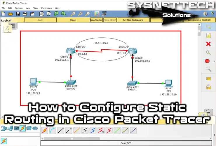
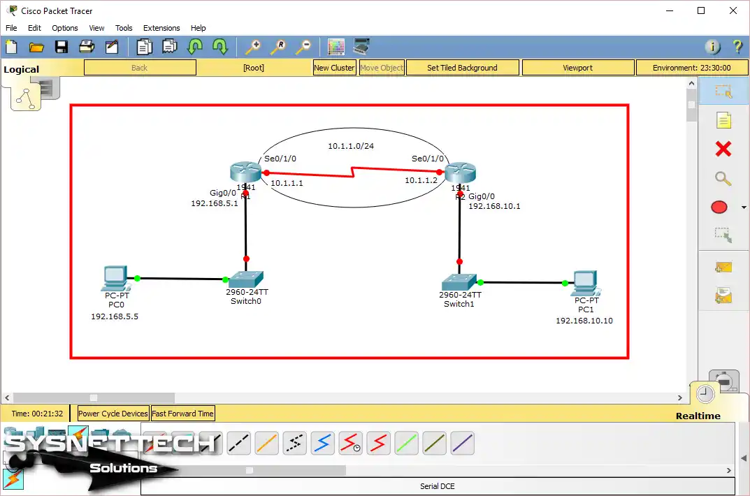
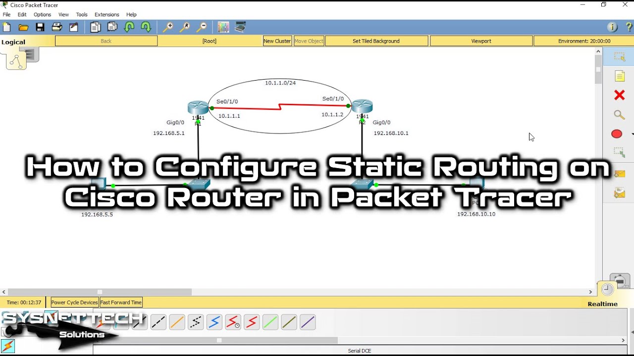
Now, let’s add static routes to the routers using Cisco Packet Tracer. To do this, follow the steps below in order, adhering to the topology shown.
1. Set Up the Interfaces on the Cisco Router
Step 1
Open the Packet Tracer program and make the network you see in the picture. Then, set up TCP/IP on the computers.
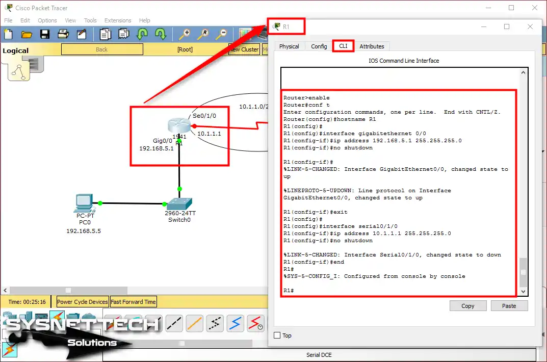
Step 2
Open the command line to set up the Gigabit & Serial ports on the Router. Here, use the interface command to set the port with these commands.
Router#conf t
Enter configuration commands, one per line. End with CNTL/Z.
Router(config)#hostname R1
R1(config)#
R1(config)#interface gigabitethernet 0/0
R1(config-if)#ip address 192.168.5.1 255.255.255.0
R1(config-if)#no shutdown
R1(config-if)#
%LINK-5-CHANGED: Interface GigabitEthernet0/0, changed state to up
%LINEPROTO-5-UPDOWN: Line protocol on Interface GigabitEthernet0/0, changed state to up
R1(config-if)#exit
R1(config)#
R1(config)#interface serial0/1/0
R1(config-if)#ip address 10.1.1.1 255.255.255.0
R1(config-if)#no shutdown
%LINK-5-CHANGED: Interface Serial0/1/0, changed state to down
R1(config-if)#end
R1#
%SYS-5-CONFIG_I: Configured from console by console
R1#
Step 3
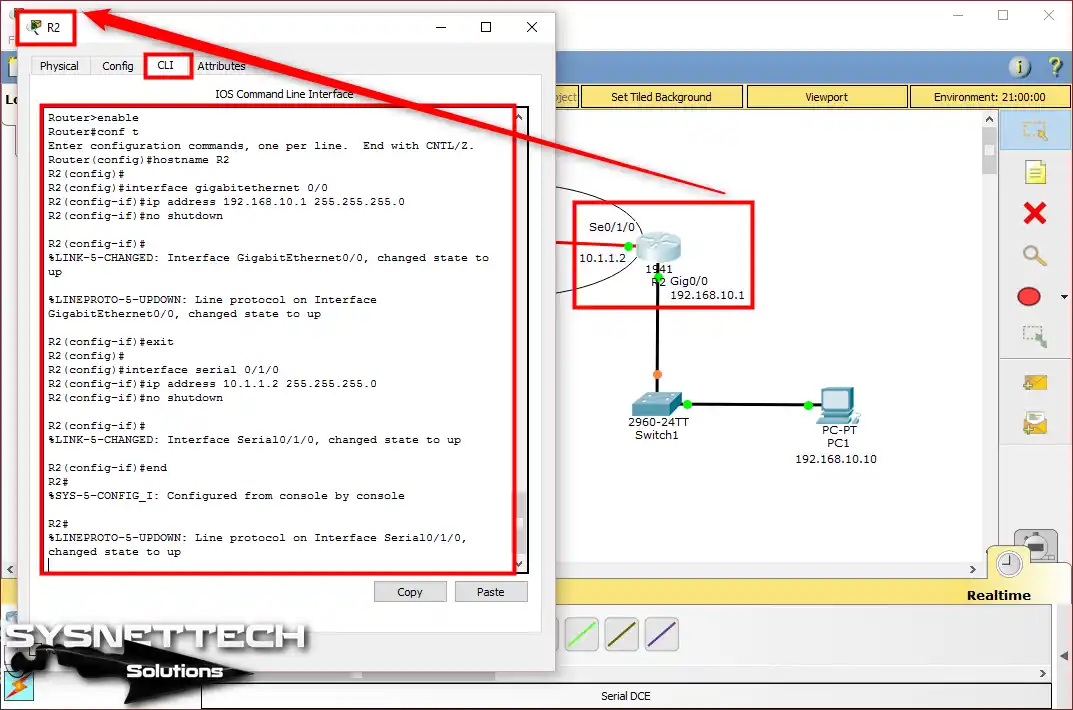
Now, set up the R2 router the same way. First, make the GigabitEthernet port work. Then, use the commands I gave to set up the Serial port.
Router#conf t
Enter configuration commands, one per line. End with CNTL/Z.
Router(config)#hostname R2
R2(config)#
R2(config)#interface gigabitethernet 0/0
R2(config-if)#ip address 192.168.10.1 255.255.255.0
R2(config-if)#no shutdown
R2(config-if)#
%LINK-5-CHANGED: Interface GigabitEthernet0/0, changed state to up
%LINEPROTO-5-UPDOWN: Line protocol on Interface GigabitEthernet0/0, changed state to up
R2(config-if)#exit
R2(config)#
R2(config)#interface serial 0/1/0
R2(config-if)#ip address 10.1.1.2 255.255.255.0
R2(config-if)#no shutdown
R2(config-if)#
%LINK-5-CHANGED: Interface Serial0/1/0, changed state to up
R2(config-if)#end
R2#
2. Test the Network Before Setting Up Static Routing
Step 1
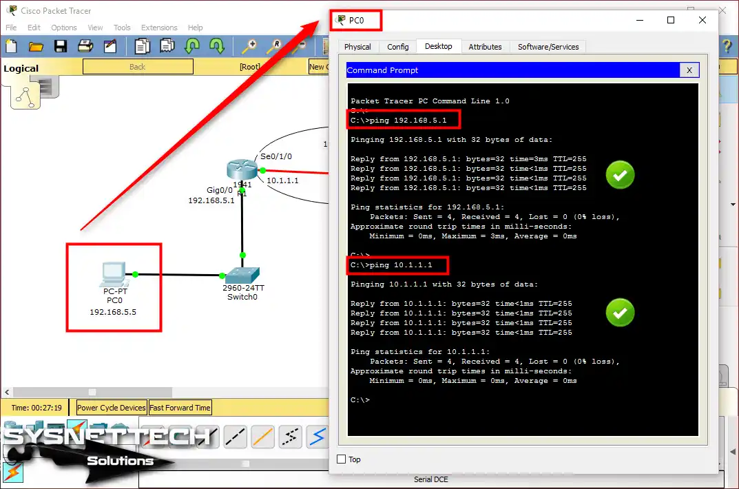
Test if the network can connect before you put static routes on the Cisco Routers. First, ping the default gateway from PC0, then ping R1’s Serial interface.
After you ping, you will see that your connection is working, like the picture shows.
Step 2
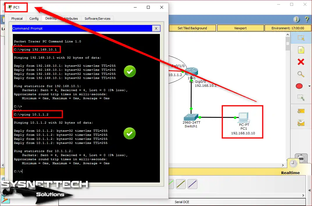
Now, ping the leading Router from PC1—also, ping R2’s serial port to check the link.
Step 3
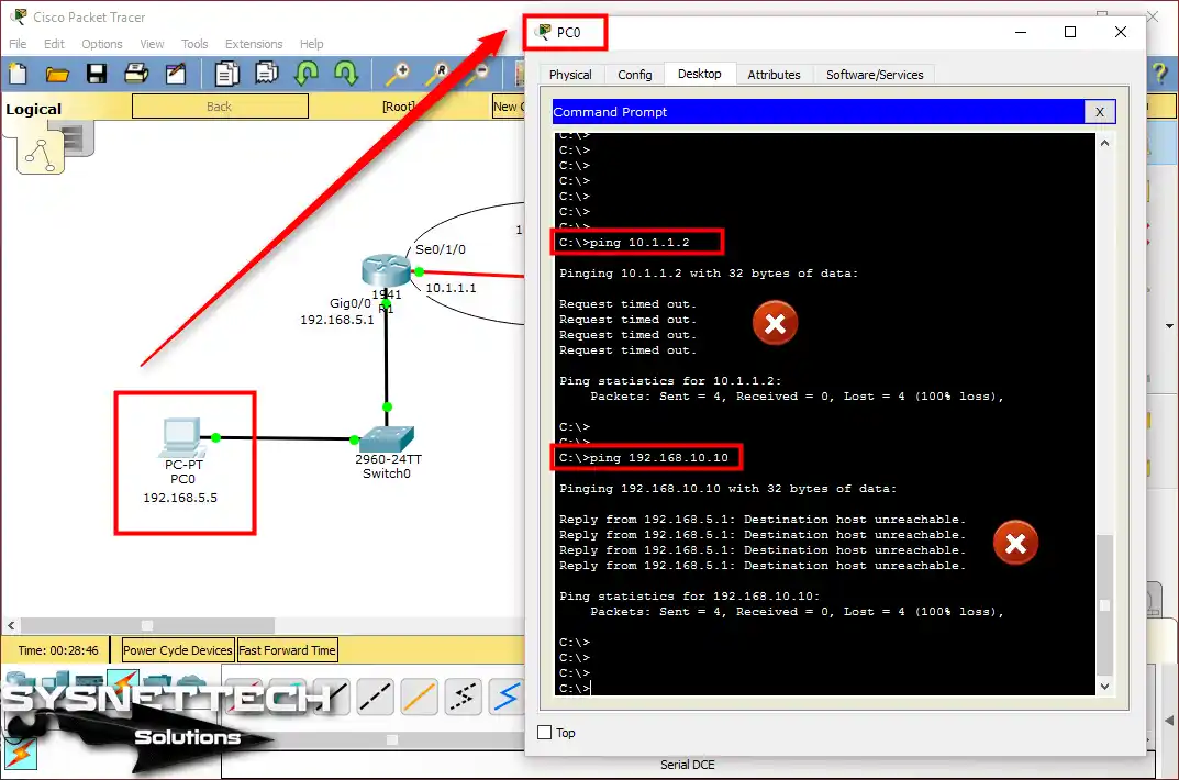
Ping the Serial interface of Cisco Router R2 from PC0 & the computer on the 192.168.5.0/24 network. However, this will not work, just like you see in the picture.
Step 4
Ping R1’s interfaces from PC1 and then check the result.
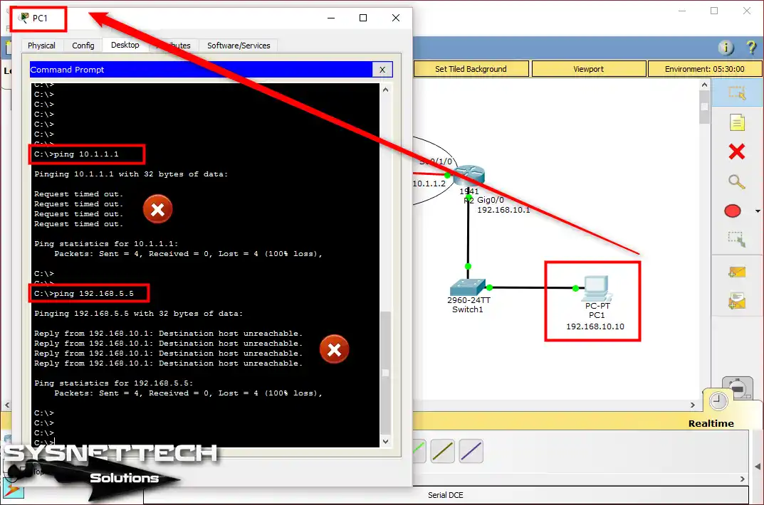
Step 5
Ping failed between clients in the two segments. This is because we did not turn on static routing for this network.
But, with this network plan, you can ping from one Router to the other. When you try it, you will see that it is successful.
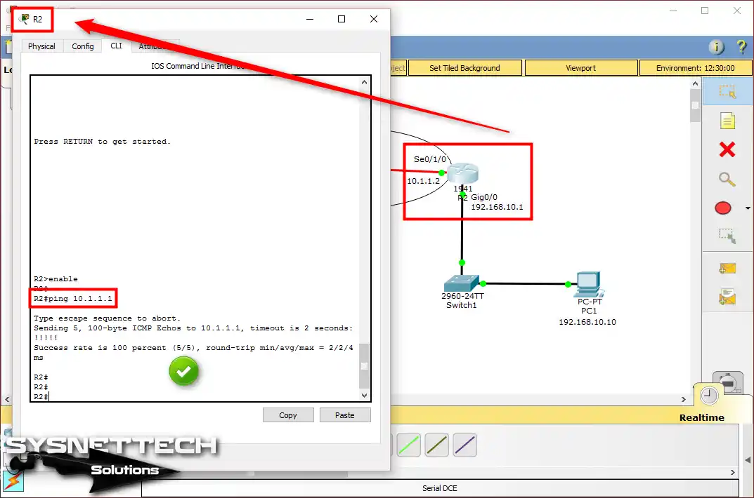
For example, you send a ping from R1 to R2. This will work just fine because both routers are on the same network.

Step 6
For example, you can try pinging R2 from R1. This process will definitely be successful. This will work for sure because the two Routers are linked directly.
3. Add Static Route to Cisco Routers
Step 1
Now, add a static route to the routers to connect PC0 and PC1. To add a static route to R1, use the command ip route 192.168.10.0 255.255.255.0 10.1.1.2.
R1#conf t
Enter configuration commands, one per line. End with CNTL/Z.
R1(config)#ip route 192.168.10.0 255.255.255.0 10.1.1.2
R1(config)#exit
R1#
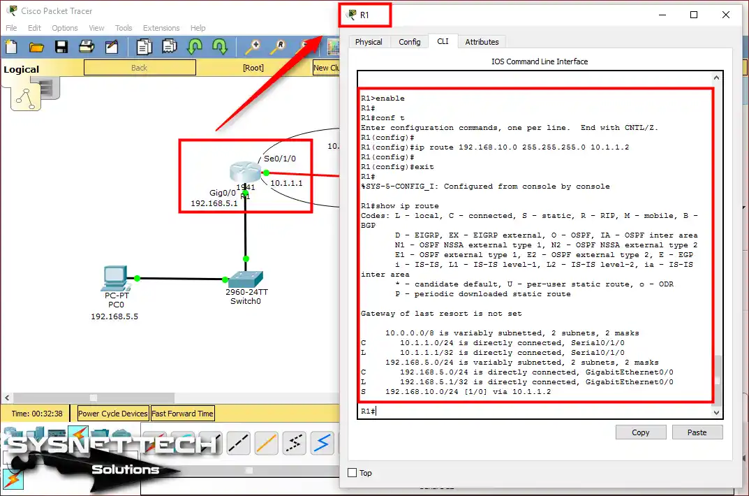
After enabling static routing on R1, run the “show ip route” command. Then, check the line S 192.168.10.0/24 [1/0] via 10.1.1.2 in the output.
R1#show ip route
Codes: L - local, C - connected, S - static, R - RIP, M - mobile, B - BGP
D - EIGRP, EX - EIGRP external, O - OSPF, IA - OSPF inter area
N1 - OSPF NSSA external type 1, N2 - OSPF NSSA external type 2
E1 - OSPF external type 1, E2 - OSPF external type 2, E - EGP
i - IS-IS, L1 - IS-IS level-1, L2 - IS-IS level-2, ia - IS-IS inter area
* - candidate default, U - per-user static route, o - ODR
P - periodic downloaded static route

Gateway of last resort is not set

10.0.0.0/8 is variably subnetted, 2 subnets, 2 masks
C 10.1.1.0/24 is directly connected, Serial0/1/0
L 10.1.1.1/32 is directly connected, Serial0/1/0
192.168.5.0/24 is variably subnetted, 2 subnets, 2 masks
C 192.168.5.0/24 is directly connected, GigabitEthernet0/0
L 192.168.5.1/32 is directly connected, GigabitEthernet0/0
S 192.168.10.0/24 [1/0] via 10.1.1.2
R1#
S 192.168.10.0/24 [1/0] via 10.1.1.2 ⇒ This line indicates that PC0 will access the 192.168.10.0/24 network via the IP address 10.1.1.2.
Step 2
To add a static route to R2, use the following command:
R2#conf t
Enter configuration commands, one per line. End with CNTL/Z.
R2(config)#
R2(config)#ip route 192.168.5.0 255.255.255.0 10.1.1.1
R2(config)#
R2(config)#exit
R2#
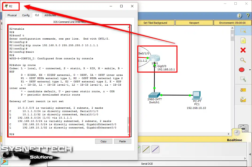
Show ip route command output in R2;
R2#show ip route
Codes: L - local, C - connected, S - static, R - RIP, M - mobile, B - BGP
D - EIGRP, EX - EIGRP external, O - OSPF, IA - OSPF inter area
N1 - OSPF NSSA external type 1, N2 - OSPF NSSA external type 2
E1 - OSPF external type 1, E2 - OSPF external type 2, E - EGP
i - IS-IS, L1 - IS-IS level-1, L2 - IS-IS level-2, ia - IS-IS inter area
* - candidate default, U - per-user static route, o - ODR
P - periodic downloaded static route

Gateway of last resort is not set

10.0.0.0/8 is variably subnetted, 2 subnets, 2 masks
C 10.1.1.0/24 is directly connected, Serial0/1/0
L 10.1.1.2/32 is directly connected, Serial0/1/0
S 192.168.5.0/24 [1/0] via 10.1.1.1
192.168.10.0/24 is variably subnetted, 2 subnets, 2 masks
C 192.168.10.0/24 is directly connected, GigabitEthernet0/0
L 192.168.10.1/32 is directly connected, GigabitEthernet0/0
R2#
S 192.168.5.0/24 [1/0] via 10.1.1.1 ⇒ This line tells PC1 how to go. It lets it reach the 192.168.5.0 network. It will use 10.1.1.1 to get there. So, all talk will go that way.
Step 3
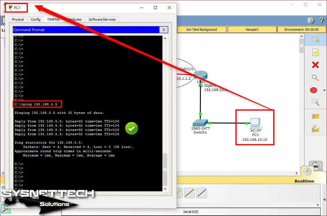
Up to this point, you have configured Static Routing on the routers in Packet Tracer. Now, ping from PC0 to PC1.
This will give you the chance to assess the connection between the two networks. Your clients in two places can talk to each other. So, their communication will now be easy and work well.
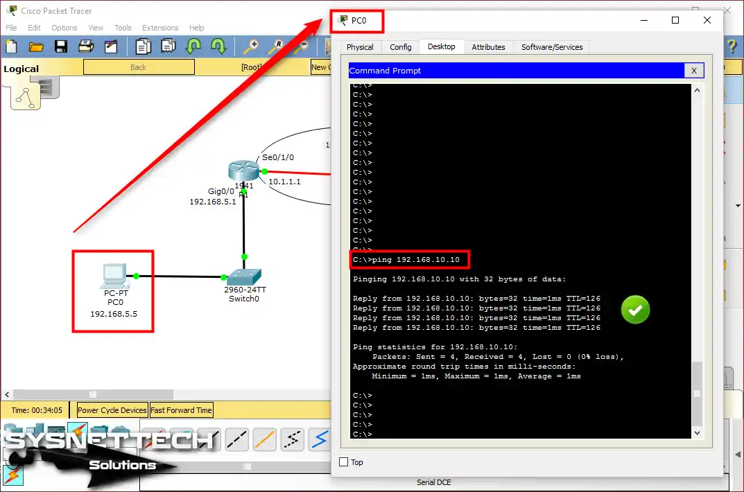
Step 4
Now, if you ping PC0 from PC1, it will work. Because we set the routing rules, two-way talk works just fine.
Show Commands for Static Routing
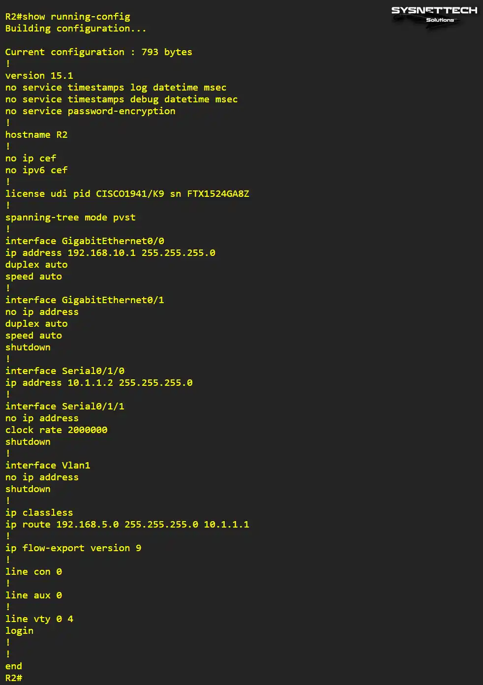
- R1# show running-config

- R2# show running-config
Static Route YouTube Training Video
To turn on static routing in Cisco Packet Tracer, watch our video below. It gives clear steps for this task. In the video, you will see real examples. These examples show how to set static paths in your network.
Also, if you like our stuff, please help us. Join our YouTube channel for news. Keep watching for more guides and network advice!
Conclusion
As a result, I successfully configured static routes on two routers using Cisco simulator software. Then, I established communication between PCs in two separate segments.
In short, with all the steps I provided, you can create an efficient and secure connection in a network environment. This method is especially preferred in structures with smaller environments. Therefore, I recommend choosing dynamic ones instead of static routing in environments that are not suitable.
Want to get better at networking? First, learn RIPv1 setup in Packet Tracer. RIPv1 is a simple routing tool. It lets routers share path details. It also helps you understand the basics of dynamic routing. Then, you can try more complex protocols.
Also, do you want to learn more about dynamic ways? If yes, try RIPv2 settings in Packet Tracer. RIPv2 is a newer type of RIPv1. It lets you use subnets and get better updates. So, this helps you handle bigger networks well.

1 Reader Comment
You are the best. Saved me alot. Please add donate button to your website.