
If you’re getting ready for Cisco exams using Cisco Packet Tracer (PT) or trying to learn more about networks, you might have to set up RIP. RIP, which stands for Routing Information Protocol, helps us figure out what determines the LANs connected to them.
Yet, since RIP runs on Version 1 by default, we have to do it ourselves. So, with this protocol, we define the LANs that Routers have. Then, it figures out which Router is closest to the area we’re trying to reach. This way, we can talk to a computer or server on there.
RIP Version 1, also known as RIPv1, uses something called “Hop” to help us get to the target network. With hop logic, we reach the faraway network from our nearby LAN in the quickest path.
That’s why we call this action “Distance Vector” routing. In this guide, we’ll show you how to set up RIP / RIPv1 using Cisco Packet Tracer.
Why Do We Use Packet Tracer for RIP (RIPv1)?
First of all, let’s explain why we use this software for the RIP routing protocol. There are many simulation tools on the market when it comes to Cisco exams. But among these is Packet Tracer, for which you don’t have to pay any fee.
This tool has a huge plus: it lets us test actual Cisco products in a virtual LAB. So, it gives us a simulated area where we can practice. In short, it prevents us from making mistakes on a real LAN when setting up devices.
Let’s say you want to test using the RIP before using it in a real network. This is helpful because it saves us money – we don’t need actual devices. Instead, we use this software that pretends to be real devices.
That’s why we use a tool called Cisco Packet Tracer. It helps us a lot. Plus, it even has a special mode that lets us see how info moves between devices in our projects. This is very good, especially for beginner networking classes.
Getting Ready for a LAB
Making a virtual network for RIPv1 is easy. So, you only need to do a few things before you start. Here’s what you should get ready:
- Learn what RIP is, think about it, and record it in your memory.
- Get the newest version of PT from the Cisco website or a safe place like ours. If you’re using a Linux OS instead of Windows, you’ll find helpful info on our website. You can install PT without any problems by checking out these resources.
- Also, to use the software, you should know some basic stuff about networks. If it’s your first time, play around with the program. Try adding devices to your topology by dragging and dropping them. Then, open their settings, give them an IP address, or connect them.
- Also, make sure you have at least two routers and two networks for RIP routing.
Creating a Network Topology for RIP / RIPv1 in Packet Tracer
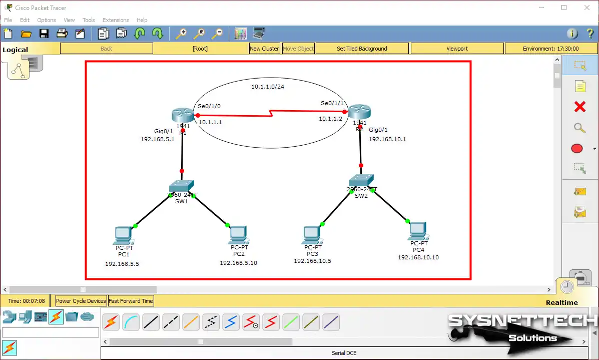
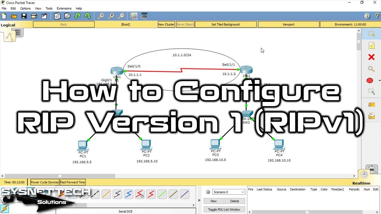
If you’re starting, Packet Tracer has a really easy-to-use interface to do this. So, when you are ready, launch it and set up a network like the image below.
But keep in mind that RIP is common in small and medium-sized networks. But, even though it’s an old method, it’s still good for you to understand.
To make a network like the picture, start by adding the devices:
- In the Device section, add two Router 1941 to the Logical workspace.
- Likewise, add two Cisco Switch 2960s.
- Lastly, add four PC-PTs.
To cable them in Packet Tracer, follow these steps:
- Link the two routers with a Serial DCE-DTE cable.
- Connect the GigabitEthernet ports of R1 and R2 Routers to the Switch (SW1/SW2) ports with a straight-through cable.
- Connect PC1 and PC2 to SW1, and PC3 and PC4 to SW2 with a straight cable.
How to Set Up RIP / RIPv1 on the Packet Tracer Router
Once you’ve done everything to get ready, you need to assign IP addresses to the network devices, as in the image. If you are going to use other IP blocks, make sure you make the correct settings. Also, it would be best if you typed the IPs of the networks you have determined under the Routers.
1. Configuring GigabitEthernet and Serial Ports
Step 1
Click on the R1 Router you made in the setup, and open the settings. After that, go to the CLI tab. Use the commands below to give IP addresses to R1’s GigabitEthernet and Serial ports.
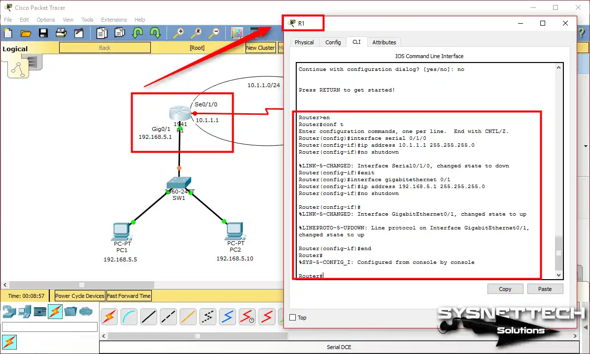
- For R1 – Se0/1/0:
R1#conf t
R1(config)#interface serial 0/1/0
R1(config-if)#ip address 10.1.1.1 255.255.255.0
R1(config-if)#no shutdown- For R1 – Gig0/1:
R1#conf t
R1(config)#interface gigabitethernet 0/1
R1(config-if)#ip address 192.168.5.1 255.255.255.0
R1(config-if)#no shutdown
Step 2
Similarly, set up the Serial0/1/1 and Gig0/1 ports on Router R2 like this:
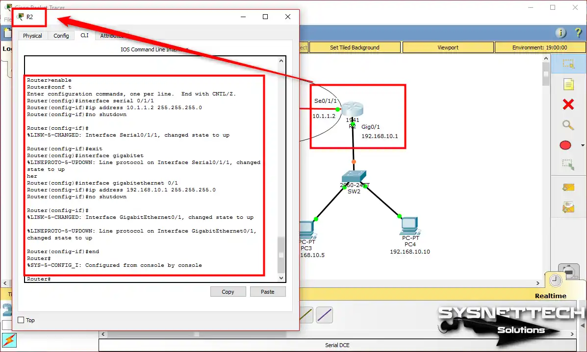
- For R2 – Se0/1/1:
R1#conf t
R1(config)#interface serial 0/1/1
R1(config-if)#ip address 10.1.1.2 255.255.255.0
R1(config-if)#no shutdown- For R2 – Gig0/1:
R1#conf t
R1(config)#interface gigabitethernet 0/1
R1(config-if)#ip address 192.168.10.1 255.255.255.0
R1(config-if)#no shutdown
Step 3
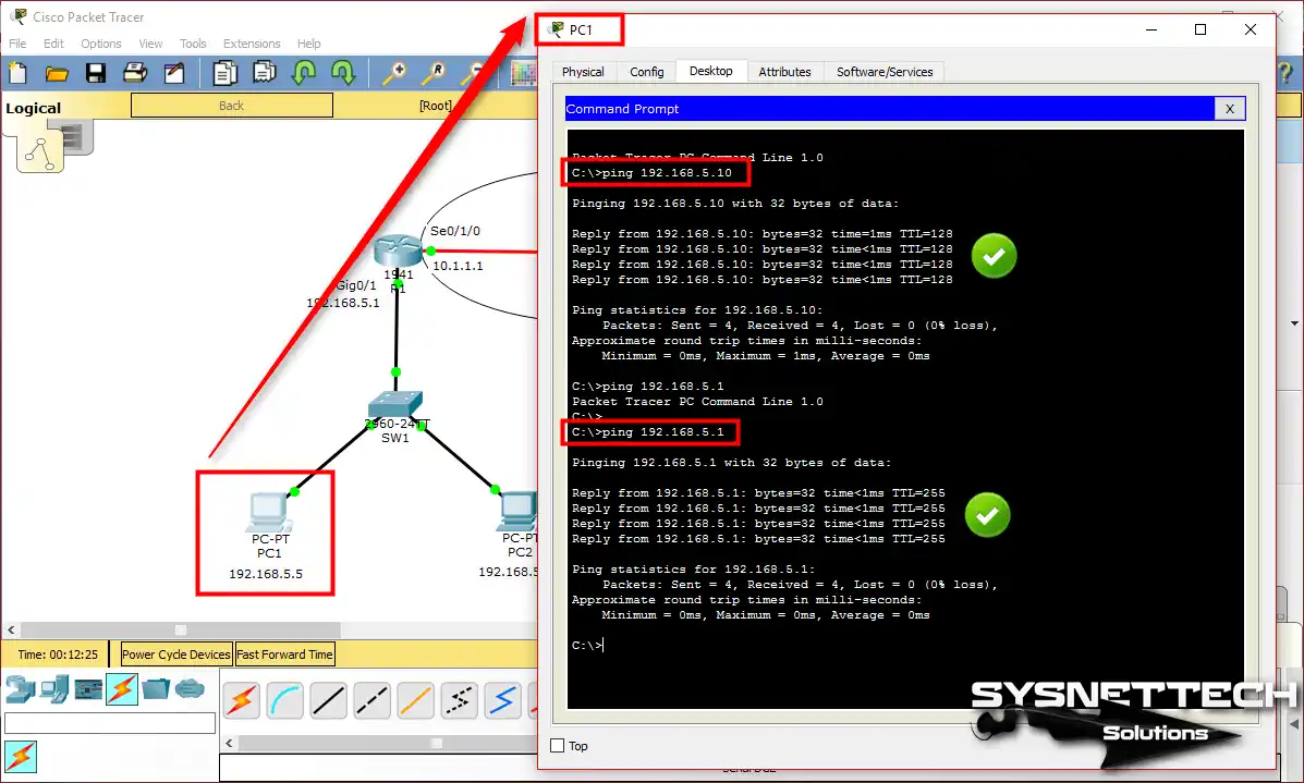
You have assigned IP addresses to Routers R1 and R2. Now, before enabling RIP, test the connection by pinging devices on LAN2 from LAN1.
Your connection from PC1 to R1’s GigabitEthernet and Serial IPs will be smooth. Because of that, PC1 and PC2 are on the same network as Router R1.
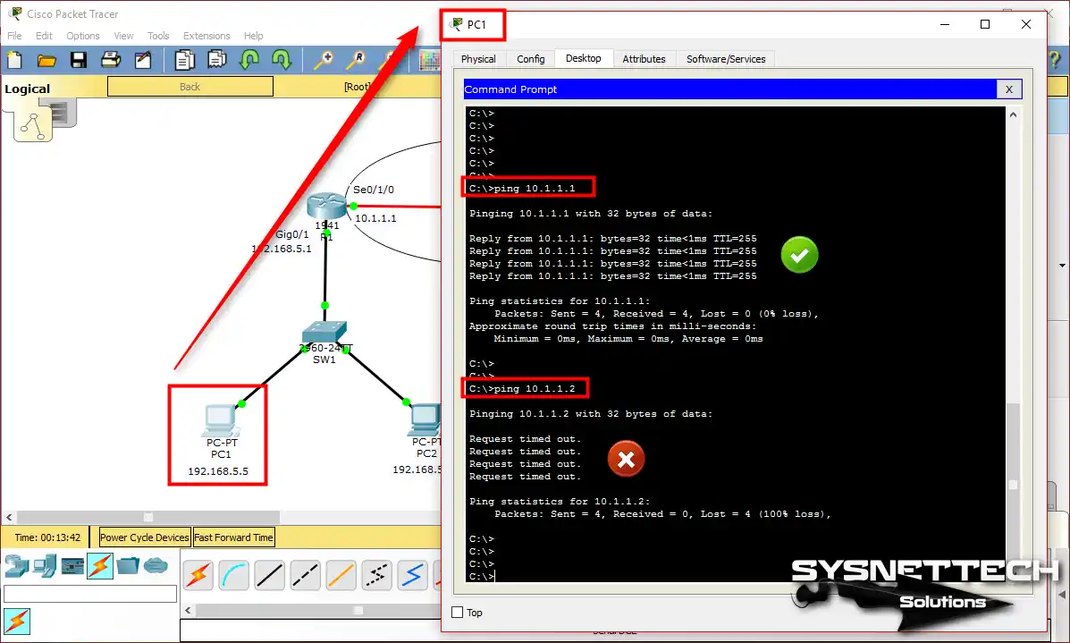
Step 4
Now, try to ping the R2 Router’s ports from the same machine, that is, PC1. At this stage, you will receive an error like the result in the image below. Because of this, routers require a Routing protocol to communicate with each other.
2. Enabling RIP Configuration
Step 1
Now, we want the PCs in LAN1 and LAN2 to talk to each other. To make this happen, let’s turn on the RIP routing protocol on the Cisco Routers R1 and R2.
Start by opening the R1 device’s CLI, then use the commands below to turn on RIP.
R1#conf t - (From the Enable mode, go to Global mode.)
R1(config)#router rip - (In Global mode, turn on RIP.)
R1(config-router)#network 192.168.5.0 - (Add the network between R1 and SW1.)
R1(config-router)#network 10.1.1.0 - (Add the network between R1 and R2.)
R1(config-router)#exit - (Go to global mode.)
R1(config)# wr - (Save the settings.)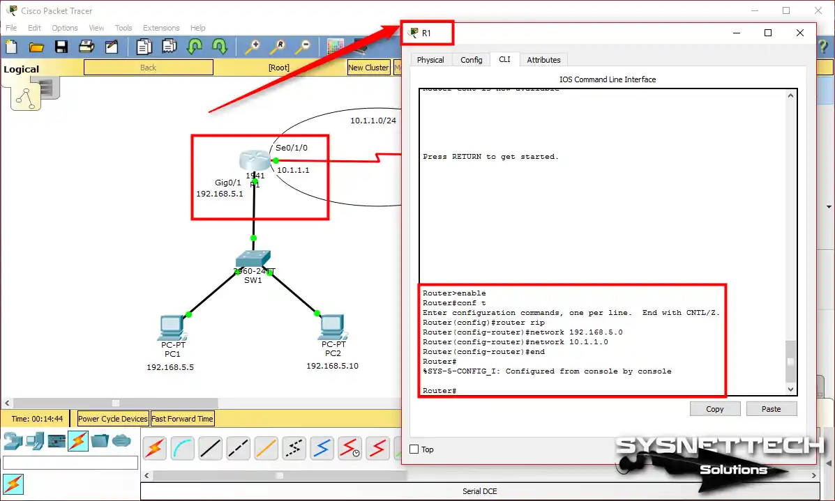
Step 2
You should apply the same steps to R2 as you did to R1. Now, follow these commands to set up RIP on R2:
R2#conf t - (Go to Global mode.)
R2(config)#router rip - (Turn on RIP Routing.)
R2(config-router)#network 192.168.10.0 - (Add the network between R2 and SW2.)
R2(config-router)#network 10.1.1.0 - (Since R1 and R2 are a single network, this value is the same.)
R2(config-router)#exit - (Now, go to the previous mode.)
R2(config)# wr - (Save what you did in R2, too.)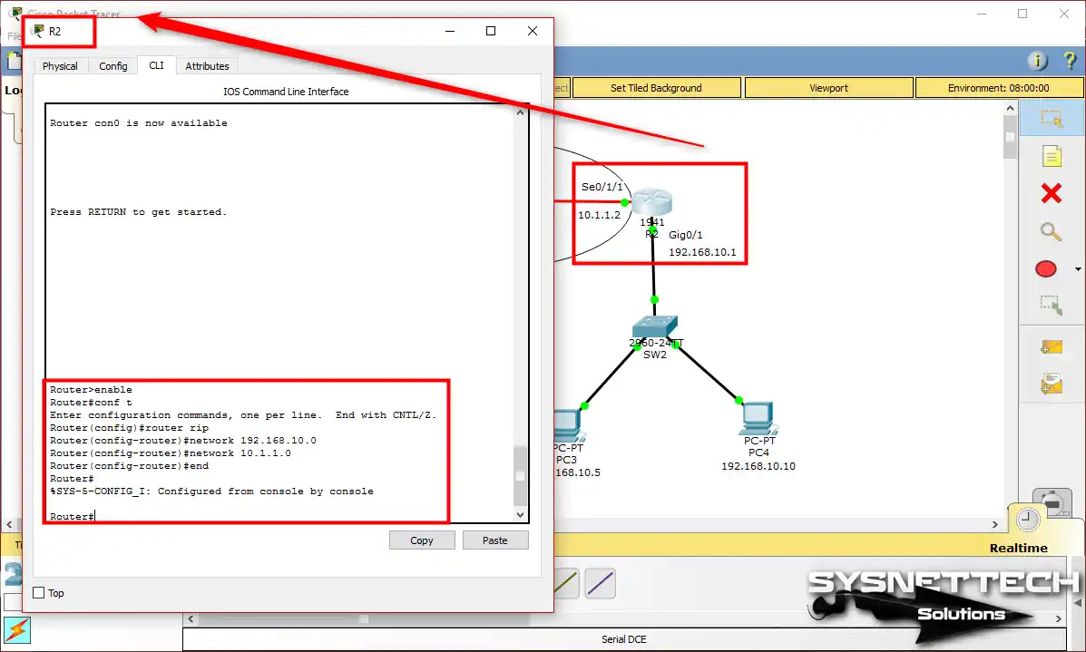
Step 3
This step is up to you. You can decide how quickly RIP updates happen. Also, you can choose how long to keep the route valid and for how long.
This step makes the network work better.
The order of the command is like: timers basic “update time” “invalid time” “holddown time.”
R1(config)# router rip
R1(config-router)# timers basic 30 180 240
3. Verify and Check RIP Settings in Packet Tracer
Make sure you set up the Routing Information Protocol correctly. You can check and test it by pinging it from your PC. But if you want to look into it more, you can use show commands from the Routers for a detailed examination.
Now, to check if RIP is working in your setup on Packet Tracer, do the following:
a) show ip route
Step 1
Once you’ve set up RIPv1, R1 and R2 devices can chat with each other. So they will share details about the networks you add with others. Now, check these routes by using the “show ip route” command.
The result of the “show ip route” command on R1 looks like this:
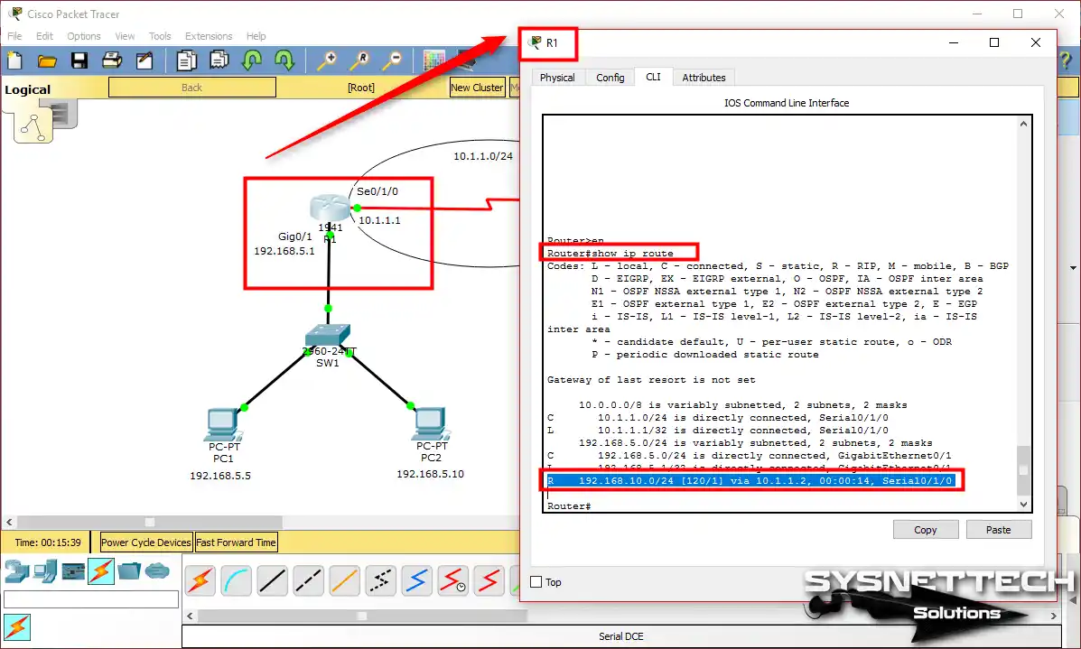
Looking at the picture, you can find the entry “R – 192.168.10.0/24 (120/1) via 10.1.1.2, 00:00:14, Serial0/1/0”. Here’s what this route record means:
- R: It means RIP is OK.
- 168.10.0/24: It shows the target network and CIDR.
- 120/1: The first number (120) indicates the metric value. The second number (1) shows the distance to the referral source.
- via 10.1.1.2: It is the IP address of the Router used to reach the routing entry.
- 00:00:14: This tells us that it learned this routing info just 14 seconds ago.
- Serial 0/1/0: It shows the output port used to reach the target.
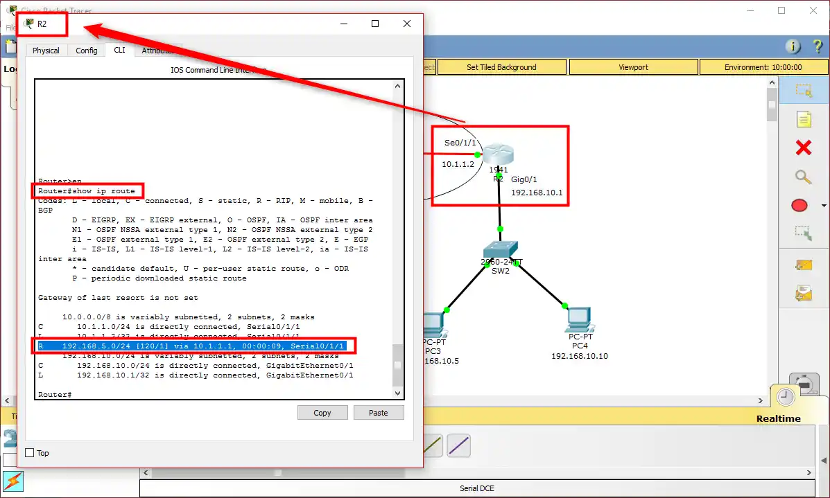
Step 2
Likewise, check the routing on Router R2. For this, run “show ip route.”
Step 3
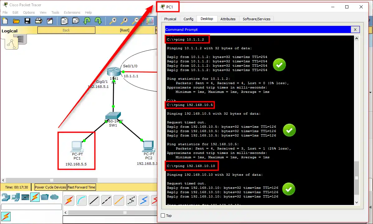
Now that you have RIP set up, try testing the connection by pinging the target network from PC1. Before, the ping didn’t work, but now Routers can talk to each other directly.
Now, ping R2’s Serial port from PC1 and Ping PC3 and PC4 on its subnet. As shown in the image, users on LAN1 can now access LAN2.
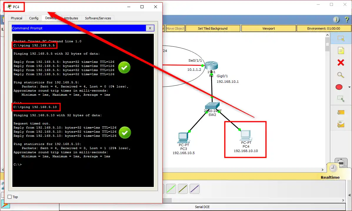
Step 4
PCs on the 192.168.10.0/24 network can also access 192.168.5.0/24, that is, LAN1, without any problems.
b) show ip protocols
Step 1
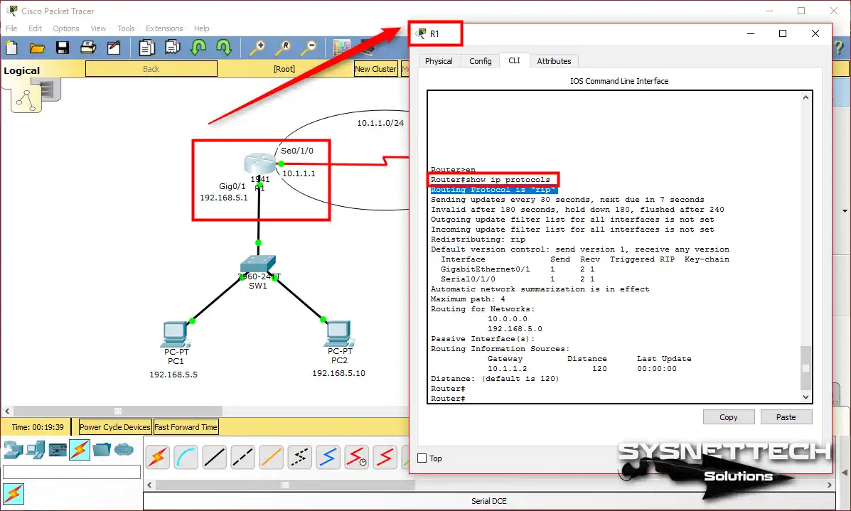
Also, you can figure out which Routing protocol is in use on the Router by using “show ip protocols.” If you run it in the CLI of the R1 device, you’ll get a notice like the one below.
The result of the command shows that the routing protocol is “rip.”
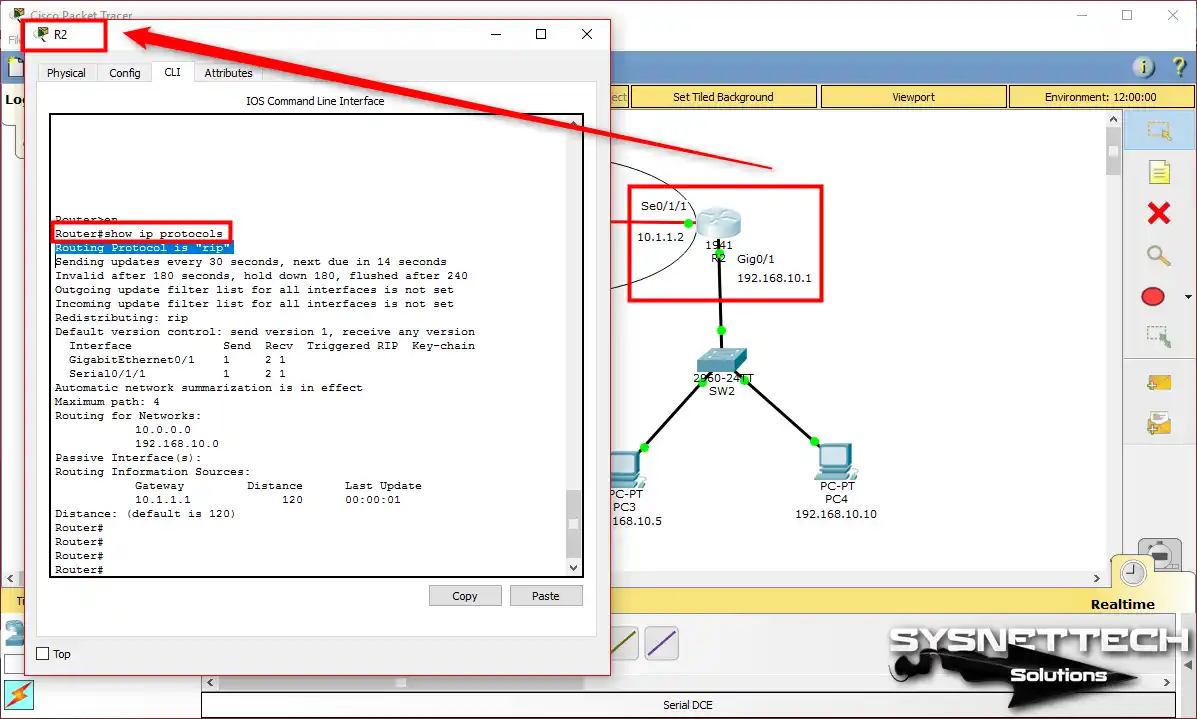
Step 2
Likewise, you can check which routing the R2 has.
Step 3
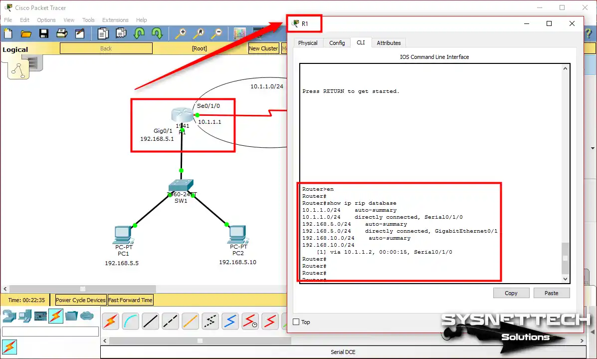
You can also see detailed routes with the “show ip rip database” command on R1.
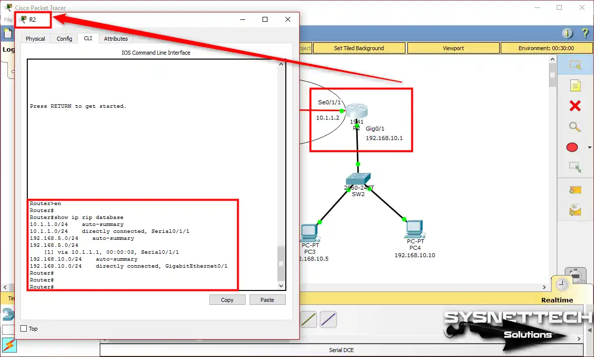
Step 4
Using the same command, check the RIP entries on R2.
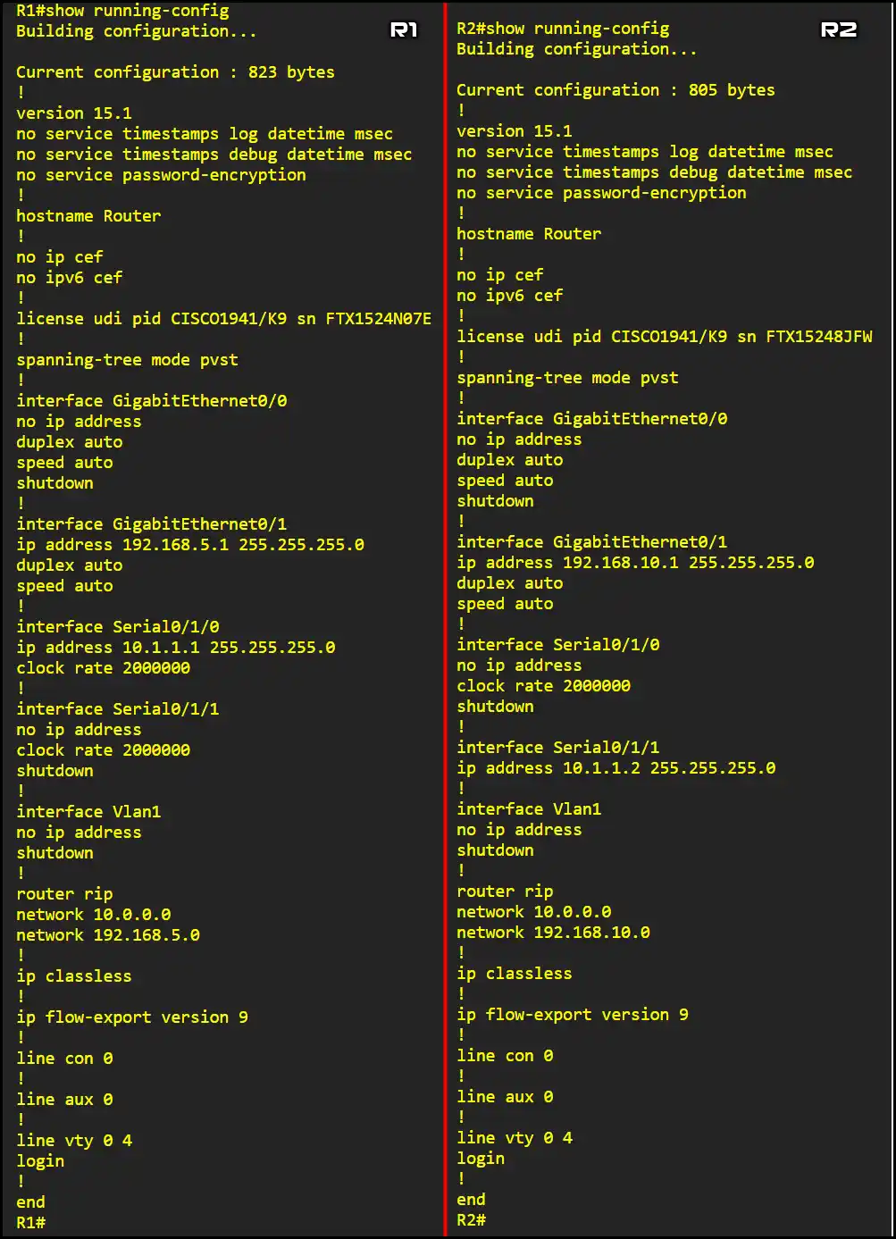
c) show running-config
Finally, take a look at the current settings with “show running-config” in the CLI of both R1 and R2 routers.
Our YouTube Training Video on the Routing Information Protocol
You can make the Routing Information Protocol step by step using Cisco Packet Tracer. To do this, you can take a look at the YouTube training guide we have prepared for you and then subscribe to us.
Frequently Asked Questions (FAQ) About RIP and Packet Tracer
- Can I use RIP in Packet Tracer?
- Can I use other routing protocols?
- Are there any resources to learn more about RIP?
Conclusion
As you can see, setting up RIP Version 1 (RIPv1) with Cisco Packet Tracer is simple. It’s something every networking pro or student should grasp because it’s basic knowledge. Even though it’s an older protocol, some places might still use it today.
So, it’s crucial to set it upright. In this guide, we’ve covered the settings for the Routing Information Protocol. As a result, make sure to check the LAN connection to be sure this protocol is working correctly.

Be the first to share your comment