
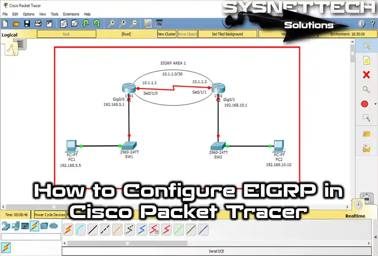
In this article, I will show you how to enable EIGRP on Cisco Routers using Cisco Packet Tracer. To give a brief introduction, EIGRP is a hybrid protocol that combines both distance vector and link state protocols. Also, this protocol is specific to Cisco devices.
In particular, I will configure EIGRP Routing settings on two routers. Then, I will explain how it provides communication between different network segments in this configuration.
How to Configure EIGRP on Cisco Routers with Packet Tracer
EIGRP (Enhanced Interior Gateway Routing Protocol) is a Hybrid Protocol routing protocol specific to Cisco devices only.
EIGRP Protocol is both a Distance Vector and Link-State routing protocol. Moreover, it sends routing tables when there is a change in the network compared to RIP. On the other hand, RIP sends routing table updates to neighboring Routers every 30 seconds.
As a result, the RIP protocol uses more network resources. That is why it creates an additional load on Routers. However, EIGRP makes specific updates when there is a change in the network.
You have learned how RIP and EIGRP are different. But RIPv2 is still a good choice for small networks. It helps you not waste IP addresses, especially because it works with VLSM. You may have noticed that this version also has simple text encryption. If you want to learn more, I explain all the RIPv2 setup steps in my article.
Meanwhile, EIGRP stands out as a hybrid protocol, while OSPF operates with pure link-state logic. The truth is, the advantages offered by the two protocols are completely different.
On big networks with different kinds of devices, OSPF can give you more options. So, I suggest you also look at the OSPF setup guide in Packet Tracer.
For more detailed information about the EIGRP protocol, visit this resource from Cisco.
How to Enable EIGRP on Packet Tracer Router
Now, let’s enable EIGRP on the Router to communicate between computers in the two LANs with the simulator software.
Step 1
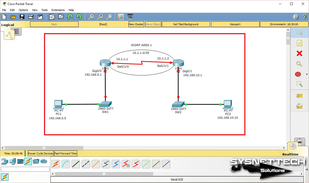
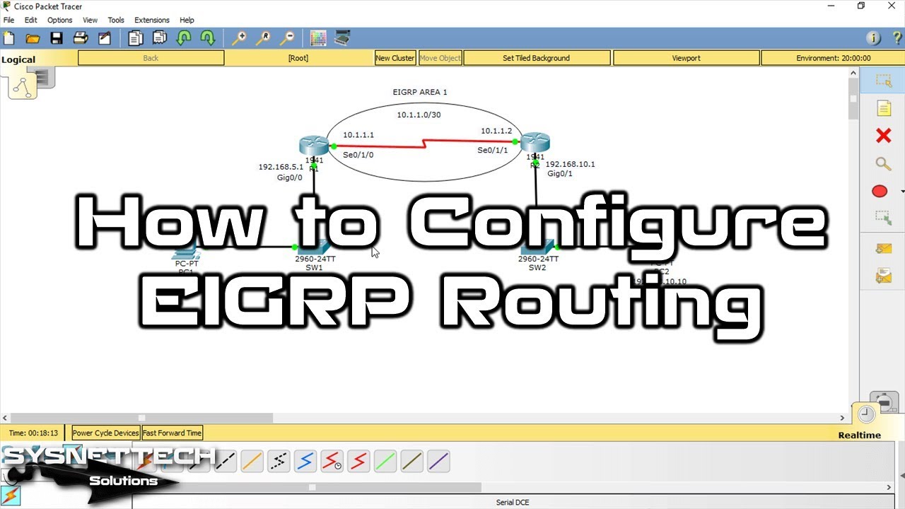
As soon as you open Packet Tracer, create a simple two-router structure for EIGRP topology, as shown below.
Determine the IP blocks for the segments and add notes to the workspace to make the design more understandable.
Making your network on the screen can be confusing. You need to learn the menus so you can add devices and connect cables. Now let’s go a bit deeper: learning how to use the Packet Tracer simulator well will show you what to do. Changing the work area to fit your needs will help you work faster.
Step 2
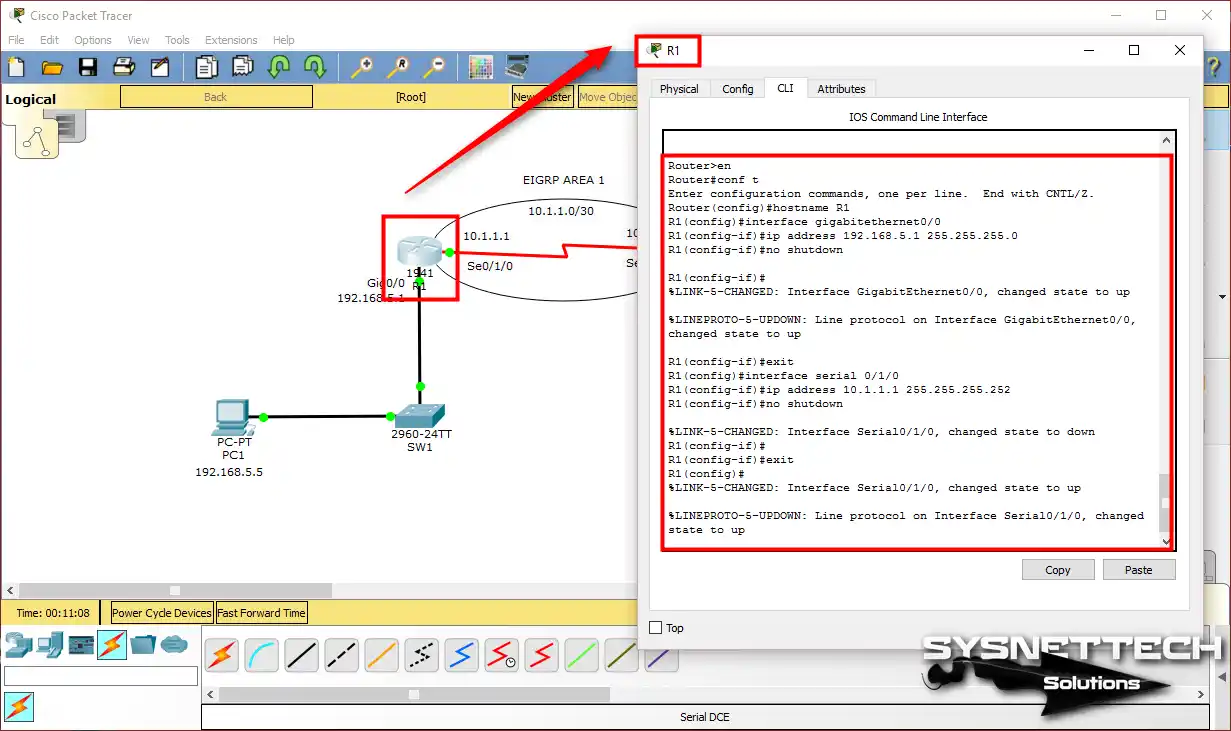
First of all, we need to configure the GigabitEthernet and Serial interfaces of Cisco Router R1 in Packet Tracer. Therefore, first, open the CLI command prompt of the R1 device and execute the commands below.
Router#conf t
Enter configuration commands, one per line. End with CNTL/Z.
Router(config)#hostname R1
R1(config)#interface gigabitethernet0/0
R1(config-if)#ip address 192.168.5.1 255.255.255.0
R1(config-if)#no shutdown
R1(config-if)#
%LINK-5-CHANGED: Interface GigabitEthernet0/0, changed state to up
%LINEPROTO-5-UPDOWN: Line protocol on Interface GigabitEthernet0/0, changed state to up
R1(config-if)#exit
R1(config)#interface serial 0/1/0
R1(config-if)#ip address 10.1.1.1 255.255.255.252
R1(config-if)#no shutdown
%LINK-5-CHANGED: Interface Serial0/1/0, changed state to down
Step 3
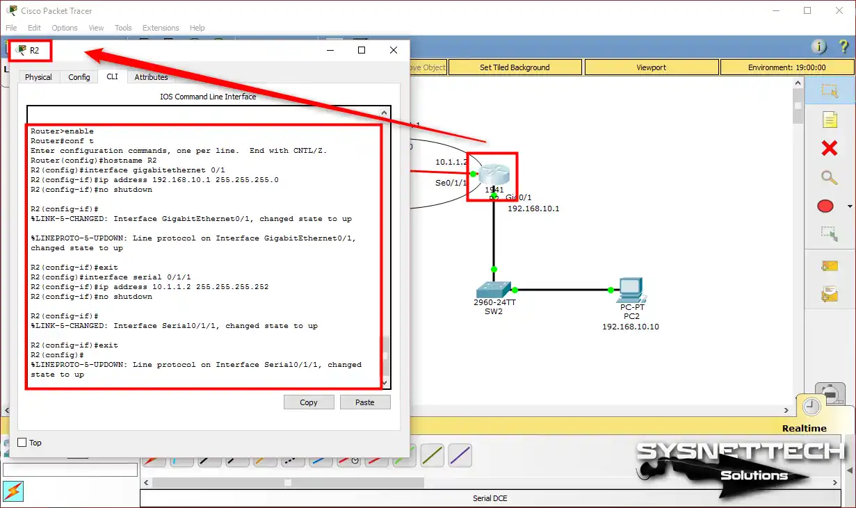
Now, edit the interfaces of Cisco Router R2 in the same way as above.
Router#conf t
Enter configuration commands, one per line. End with CNTL/Z.
Router(config)#hostname R2
R2(config)#interface gigabitethernet 0/1
R2(config-if)#ip address 192.168.10.1 255.255.255.0
R2(config-if)#no shutdown
R2(config-if)#
%LINK-5-CHANGED: Interface GigabitEthernet0/1, changed state to up
%LINEPROTO-5-UPDOWN: Line protocol on Interface GigabitEthernet0/1, changed state to up
R2(config-if)#exit
R2(config)#interface serial 0/1/1
R2(config-if)#ip address 10.1.1.2 255.255.255.252
R2(config-if)#no shutdown
%LINK-5-CHANGED: Interface Serial0/1/1, changed state to up
R2(config)#
Step 4
I have not configured EIGRP Routing on the Routers yet! Now, test the connection by Pinging R1’s GigabitEthernet0/0 and Serial0/1/0 interfaces from PC1.
As you can see in the image below, the PC on the 5.0/24 network can access the Router in its area.

Step 5
Similarly, test the interfaces of Router R2 via PC2 on the 192.168.10.0/24 network.

Step 6
This time, when you ping R2’s Serial0/1/1 interface from PC1 and PC2, you will see that the operation fails. Because of that, we have not configured any routing protocols, such as EIGRP, in this network environment.

Step 7
Before configuring the vector and link-state protocol, you will also not be able to ping the R1 interfaces from PC2.
Note: The ping did not work because the routers do not know the faraway network. You need to learn the basics of static routing before you use dynamic protocols. Many people make this mistake and skip straight to dynamic protocols. But adding routes by hand helps you understand how it all works. For the basic steps, be sure to read my article on static routing.

Step 8
To enable EIGRP routing, open R1’s CLI command prompt. Then, apply the commands that I wrote for you below. Note that the first command you will use here is router eigrp (AS Number).
R1#conf t
Enter configuration commands, one per line. End with CNTL/Z.
R1(config)#
R1(config)#router eigrp ?
Autonomous system number
R1(config)#router eigrp 1
R1(config-router)#network 192.168.5.0 ?
A.B.C.D EIGRP wild card bits

R1(config-router)#network 192.168.5.0 0.0.0.255
R1(config-router)#network 10.1.1.0 0.0.0.3
R1(config-router)#end
R1#
%SYS-5-CONFIG_I: Configured from console by console
R1#

Step 9
In the Packet Tracer topology, this time, the EIGRP protocol on R2 is enabled.
R2#conf t
Enter configuration commands, one per line. End with CNTL/Z.
R2(config)#
R2(config)#router eigrp 1
R2(config-router)#network 192.168.10.0 0.0.0.255
R2(config-router)#network 10.1.1.0 0.0.0.3
R2(config-router)#
%DUAL-5-NBRCHANGE: IP-EIGRP 1: Neighbor 10.1.1.1 (Serial0/1/1) is up: new adjacency
R2(config-router)#end
R2#

Step 10
You can view the routing table using the show ip route command on R1. The routing protocol is indicated by the letter D, as in the image below, and its metric is 90.

Step 11
Display the routing table on Router R2 with the show ip route command.

Step 12
After configuring routing on the routers, devices in the two segments will now be able to communicate with each other.
Additionally, you can test and troubleshoot routing protocol operations with EIGRP show commands. Example show commands are as follows.
show ip eigrp neighbors
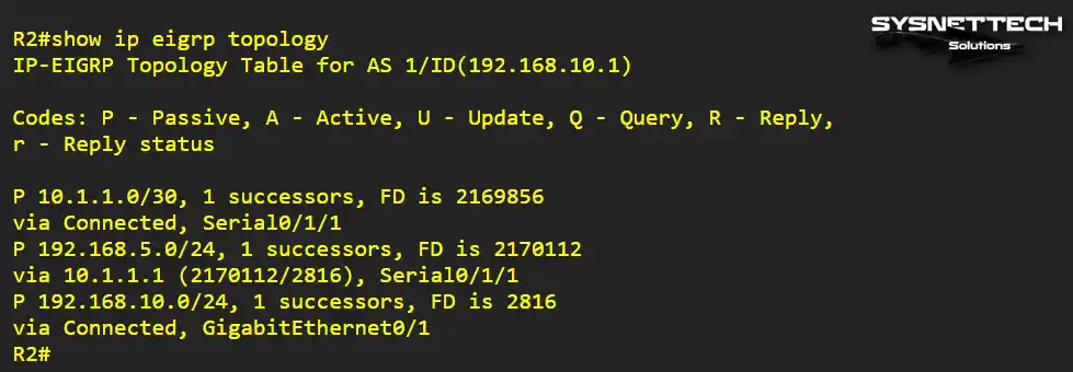
show ip eigrp topology
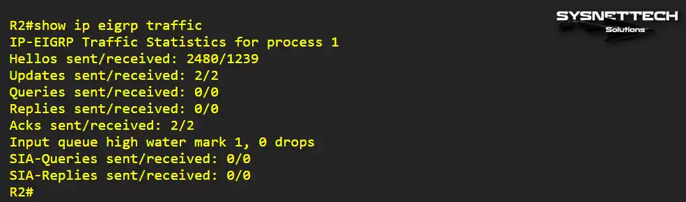
show ip eigrp traffic

Step 13
Examine the neighborhood information, topology map, and traffic flow by using the show commands on Router R2.

Step 14
To troubleshoot EIGRP, you can use the debug eigrp packets command in privileged mode.
debug eigrp packets
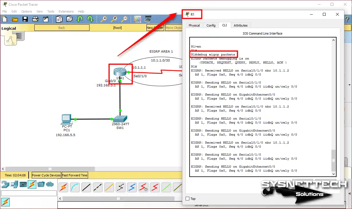
Step 15
Likewise, you can analyze packages on R2 with the debug command.

Show Commands for EIGRP Routing
- R1# show ip route

- R2# show ip route

- R1# show ip eigrp neighbors

- R1# show ip eigrp topology

- R1# show ip eigrp traffic

- R2# show ip eigrp neighbors

- R2# show ip eigrp topology
- R2# show ip eigrp traffic
- R1# debug eigrp packets

- R2# debug eigrp packets

- R1# show running-config

- R2# show running-config

Video
Conclusion
In this article, we configured EIGRP routing in a Packet Tracer topology with two routers using Cisco network simulator software. I recommend using this routing protocol in larger network designs.
On the other hand, the only disadvantage of this protocol is that it is only valid on Cisco devices. For this reason, you should choose one of the routing protocols that best suits your structure. Thanks for following us!

Be the first to share your comment