

An IDE storage drive is the most basic hardware component of a computer case. However, in the 1990s and 2000s, it connected to the motherboard with huge ribbon cables. Now it forms the foundation of the Integrated Drive Electronics standard. That standard is the ancestor of today’s compact SATA and NVMe M.2 drives.
Countless old magnetic disk drives with this hardware interface still circulate in the market. They hold family photos, old projects, or critical industrial software. These drives contain delicate parts in their mechanical assembly. The spindle motor, voice coil actuator, and read-write heads are examples.
Moreover, the IDE port is indispensable for hardware enthusiasts who build retro gaming PCs. My goal is to teach you this storage technology down to the finest hardware detail. Also, you will discover its signal timing and mechanical features.
In this article, we first dive into the history of the hard disk drive and basic hardware definitions. We will cover concepts like magnetic platter geometry, sector density, and access time. Next, we examine the physical structure and pinouts. Also, we will learn about 40- and 80-conductor data cable types.
Then, we will tackle the classic master-slave jumper settings step by step. We will also explain the logic of channel sharing. Finally, I will show you how to revive old magnetic disk drives with modern converters. I will even tell you how to fix disk detection issues in the motherboard BIOS.
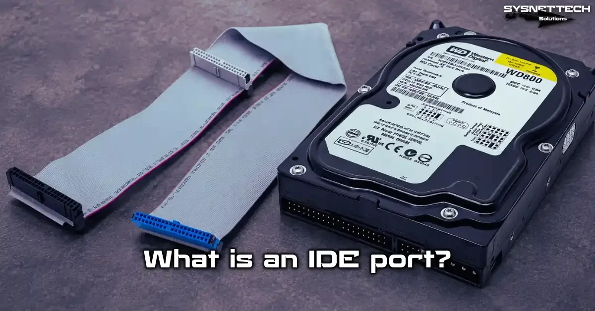
What Is IDE (Integrated Drive Electronics)? Basic Definition & History
Integrated Drive Electronics revolutionized personal computer hardware in the late 1980s. This technology moved the disk controller directly onto the drive’s PCB.
Previously, the controller sat on a separate ISA expansion card. It also connected to the drive with a set of signal cables. Thanks to this hardware integration, production costs dropped significantly.
At the same time, signal losses on the motherboard bus also decreased greatly. Electromagnetic interference and signal reflection issues also eased. Communication between the magnetic platters and the motherboard became much more reliable.
The drive started using its own controller firmware. It also handled bad sector management with error correction codes (ECC).
The IDE storage standard managed the hard disk drives of millions of PCs for many years. Whether in desktop cases or industrial embedded systems, you see this hardware interface everywhere.
Today, we see it more as a piece of computer hardware history. However, this legacy still plays a vital role in modern data recovery scenarios.
This hardware knowledge is essential for rescuing digital heritage from old magnetic disks. The drive has rotation speed (RPM) and average seek time specifications. Also, these details directly affect the data recovery strategy. The cache buffer size is also a key factor.
IDE’s Full Name and Its Relationship with PATA: What Is PATA? Are PATA and IDE the Same?
The acronym comes from the initials of “Integrated Drive Electronics.” This name describes the idea of controller integration in its simplest form. Over time, this hardware technology officially became the ATA (AT Attachment) standard.
When Serial ATA entered the market, a need for a backward name arose. That’s exactly when the term “PATA”—Parallel ATA—emerged.
In practice, PATA and IDE refer to the same hardware interface. Many IT professionals in the industry use the two terms interchangeably. For example, if a motherboard manual says “PATA connector,” know that it means the classic parallel port.
The main difference here is purely based on technical literature. Namely, IDE is an original commercial and technical concept. On the other hand, PATA is a marketing name coined to distinguish the serial storage technology.
You often see the phrase “Enhanced IDE” on labels of old hard disk drives. This phrase defines an advanced version of the standard. Also, thanks to the ATAPI protocol, optical drives like CD-ROM and DVD-ROM could connect to the same bus.
Therefore, knowing they are synonyms makes finding a storage interface today much easier. The same 40-pin IDC connector, ribbon cable, and BIOS settings are common for all these drives.
History of the IDE Interface: When Was It Invented? Western Digital and Compaq Collaboration
This revolutionary hardware idea emerged in 1986 from the joint minds of Western Digital and Compaq engineers. The main goal was to lower hard disk production costs and increase hardware compatibility.
Previously used storage interfaces like ST-506 and ESDI were complex and expensive. Moreover, compatibility issues between drives and controller cards frustrated technicians.
This new approach solved all these problems at the root by integrating the controller directly into the drive electronics.
Now the drive’s own controller independently managed servo pattern reading and head positioning operations. It also took on the data encoding task.
ANSI approved the first official ATA specification, ATA-1, in 1994. This hardware standard offered 16-bit parallel data transfer and PIO mode 0 support.
Then storage technology advanced at an incredible pace. First, EIDE (Enhanced IDE) brought support for four devices. Next, ATA-2, ATA-3, and ATA-4 versions arrived. Thus, developers continuously pushed transfer speed and capacity limits higher.
For example, thanks to Ultra DMA modes, the theoretical interface bandwidth reached 133 MB/s. This speed was an incredible threshold for magnetic platters spinning at 7200 RPM. In the same period, the SMART feature arrived, making it possible to monitor drive health.
This evolution is a turning point for personal computer storage. Users could now connect up to two hard disk drives directly to their motherboards.
In the following years, the curtain slowly closed with the rise of Serial ATA in the early 2000s. Despite this, this parallel standard lived on. It remained on motherboards as an integrated IDE controller until the mid-2000s.
Even today, you can still encounter this old storage hardware in industrial embedded systems.
IDE Port and Cable: Physical Structure, Types, and Pinout
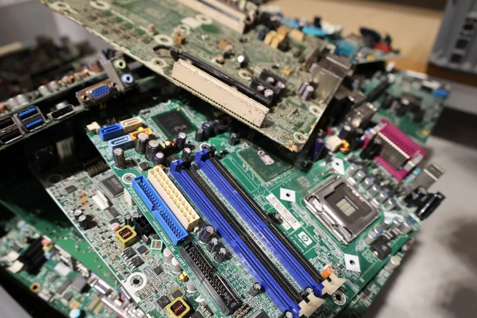
Knowing the port’s physical structure eliminates hardware connection errors. On the motherboard, you usually see a black or blue 40-pin rectangular male connector.
Right next to it, there is a space for a Molex 4-pin power connector. On the drive side, you find the female version of the same structure and a DC power input.
These two physical connections separate the data signal and power flow from each other. They also supply the necessary +12V and +5V power for the spindle motor and voice coil actuator. The controller logic circuit also uses this power.
Interestingly, the blue color of the IDE port usually depends on the manufacturer’s preference. However, typically, the primary channel is blue and the secondary channel is black.
This color coding serves as a visual guide when setting the boot order in the BIOS. Similarly, the IDE cable color code follows a standard.
Namely, we connect the blue connector to the motherboard. Black goes to the master drive, and gray goes to the slave drive. These colors are mandatory. They appear at the hardware level, especially with the 80-conductor data cable standard.
Pinout, Signals, and Connection Warning
We call the connector itself a 40-pin IDC connector. The pins sit in two rows, and each carries a different signal.
For example, pin 1 holds the reset signal. Pin 28 carries the CSEL signal. Also, system resources like I/O port address 0x01F0 link to this motherboard port.
IRQ 14 and 15 also connect here. This physical and logical structure forms the basis for device numbering and channel sharing. Signal integrity is maintained, and data line grounding pins are strategically placed.
How Many Pins Does an IDE Cable Have? 40-Pin vs. 80-Wire Difference and 40-Conductor – 80-Conductor Detail
The answer to this question depends on the type of cable you use. First-generation cables had 40 conductors and 40 pins. Each pin physically corresponded to one wire.
However, as disk speeds and data transfer rates increased, this simple structure became inadequate. Crosstalk emerged during parallel data transmission at high frequencies.
Ground-level noise compounded the problem. To solve this, engineers developed an ingenious method.
New-generation cables still use 40 pins, but they contain 80 conductor wires inside. How is this possible? Very simple: They add an extra ground wire between each existing signal and ground line.
This 80-conductor cable noise reduction technique dramatically increases signal cleanliness. As a result, you achieve Ultra ATA/66 speeds and above.
You should use an 80-wire cable instead of an old 40-wire cable. Otherwise, you limit the drive speed to UDMA mode 2.
On the other hand, cable length is also critical for signal quality. Therefore, the official maximum length limit for an IDE cable is 18 inches.
| Feature | 40 Conductor (40 Wire) | 80 Conductor (80 Wire) |
|---|---|---|
| Connector Pin Count | 40 pin | 40 pin |
| Number of Wires Inside | 40 wire | 80 wire |
| Supported Max Speed | Ultra ATA/33 (UDMA 2) | Ultra ATA/133 (UDMA 6) |
| Connector Colors | Generally black (single color) | Blue (motherboard), Black (Master), Gray (Slave) |
| Noise Reduction | None | Yes (Extra ground lines) |
| Signal Integrity | Low | High |
When recovering data from an old magnetic disk, definitely use an 80-wire ribbon cable. Otherwise, data integrity is at risk. Personally, I strictly apply this rule in all my field recovery jobs.
Red Stripe, Color Code, and Connector Orientation
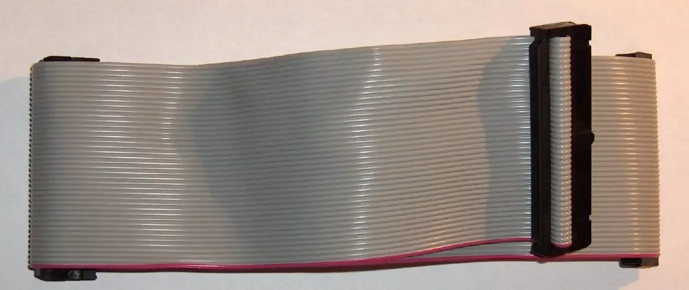
You definitely see a red stripe on one edge of an IDE cable. This red line is a hardware reference that marks pin 1. It is a vital sign.
If you plug the cable in the wrong orientation, the system won’t boot. It may not see the drive at all. Fortunately, we have a few simple methods to find the right direction.
- Find the Red Stripe: One side of the ribbon cable has a red or dashed mark. This mark always aligns with pin 1.
- Look at the Power Connector: Use the Molex power input on the drive as a reference. The red stripe is almost always on the side facing the power connector.
- Check the Motherboard Mark: The port on the motherboard usually has a “1” or an arrow. Align the red stripe with that side.
- Follow the Color Code: On an 80-wire cable, plug the blue end into the motherboard. Plug the black end into the master drive. Connect the gray end to the slave drive if present. This follows the host middle end connector logic.
- Use the Blind Spot: One pin hole in the middle of the connector is blocked. This prevents you from plugging it in backwards. Never force it.
With these simple steps, you can make the connection correctly every time. Remember, the most critical point here is the position of the red stripe.
What Is a Laptop 44-Pin Drive? 40-Pin vs. 44-Pin Difference and Adapter Usage
In desktop systems, we use the standard 40-pin connector. But in laptop hardware, things change. The 2.5-inch drives developed for laptops use a 44-pin mobile PATA interface.
The main difference is that the extra four pins carry DC power directly. In a desktop, the Molex 4-pin power connector is separate. But a laptop hard disk takes both data and power from the same tiny connector.
This is an excellent engineering solution for space saving. These tiny drives usually have a speed of 4200 or 5400 RPM. Also, their power consumption is lower.
Today, a 44-pin to 40-pin adapter is essential for reading these old laptop disks. This adapter converts the 44-pin output to a standard 40-pin data line. It also provides a separate power input.
This way, you connect the drive to a normal desktop IDE channel. You can also plug it into an external converter. Especially when recovering old family photos, these adapters are lifesavers.
Also, when using these adapters, reference the red stripe and blind spot. This helps you find the correct orientation. However, be careful, as laptop disk drives are more delicate.
If you supply power incorrectly, the drive electronics suffer damage instantly. Therefore, do not power on before double-checking the connection.
Also, various solutions exist to connect Compact Flash cards to the storage port of old laptops. For example, you can use a CF to IDE adapter or an SD to IDE adapter.
Master, Slave, and Cable Select: IDE Jumper Settings
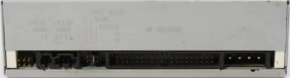
The most confusing part of this storage interface is the jumper settings. It also tests your patience. You can connect two hard disk drives to a single ribbon cable.
But the system needs to understand which one is primary and which is secondary. That’s where the jumper block configuration comes in.
These tiny plastic pieces determine the drive’s hardware identity on the circuit. A wrong setting causes the disk not to appear in the BIOS or prevents the system from booting.
In the past, the most common question I heard in a computer shop was “What is master/slave?” Actually, this is a matter of hardware hierarchy. The master holds control of the data bus. The slave communicates only when the master allows it.
This structure is mandatory to avoid bus contention. Today, this mechanism may seem primitive to you. However, for that era, it was an extremely effective channel sharing method. DASP and PDIAG signals also play a role in this identification.
What Are Master and Slave? Jumper Settings and Pin Layout
On the back of an IDE drive, you see a row of pins. They sit next to the data and power connectors. This pin layout usually ranges from 4 to 10 pins.
By placing a plastic jumper over the pins, you set the drive’s hardware role. We call these roles Master, Slave, and Cable Select.
Also, special modes like “Single” exist for standalone use. “Master with non-ATA slave” mode is also available.
- Read the Drive Label: Every disk has a jumper diagram stuck on it. This diagram shows which pins to close. Most often, you short the left two pins for Master. For Slave, you close the right two pins.
- For a Single Disk: Plug the drive into the connector at the far end (black) of the IDE cable. Set the jumper to “Master” or “Single Drive.” If no “Single” mode exists, setting it as master is enough.
- For Dual Disks: Plug the first disk into the black end and set it as Master. Then plug the second disk into the middle gray end and set it as Slave. This is standard for dual-drive configuration.
- Master with Slave Present: If a slave exists in the system, jumper the master disk as “Master with slave.” This mode tells the disk that another device is on the bus.
- Apply Power Last: Connect the data cable first, then the Molex power. This sequence is safer for the motherboard and drive electronics.
Using tweezers makes this job much easier when setting these jumpers. Especially in tight cases, plugging and removing jumpers by hand can be frustrating.
A wrong jumper setting does not physically damage your disk. But it completely blocks your access to the data.
Cable Select (CS) Mode, Single Disk Mode, and Primary/Secondary Channels
If you don’t want to deal with jumper settings, Cable Select comes to the rescue. In this mode, you set all drives’ jumpers to the CS position.
The cable decides, not you. How? If you use a special 80-conductor cable, the CSEL signal is activated.
The black connector at the end automatically becomes Master. The middle gray connector acts as Slave. Brands like Compaq and Dell used this method heavily in their OEM systems.
However, there are usually two ports on the motherboard. These are the primary IDE and secondary IDE channels. Each channel can manage two devices within itself. Thus, you can connect up to four storage devices in total.
So, what are primary and secondary IDE channels? The primary channel usually holds the boot disk and operating system. The secondary channel is for CD-ROM or backup storage. This configuration allows system resources to be distributed more efficiently.
If you use a single disk, IDE Single disk mode is the healthiest method. You set the disk as master on the primary channel. This way, the system finds the disk quickly during boot.
Otherwise, the system behaves as if a slave disk exists. This causes a timeout and slows down the boot. Nowadays, knowing these details is vital when setting up retro computer solutions.
IDE Hard Disk, Optical Drive, and Device Connection: Step-by-Step Setup
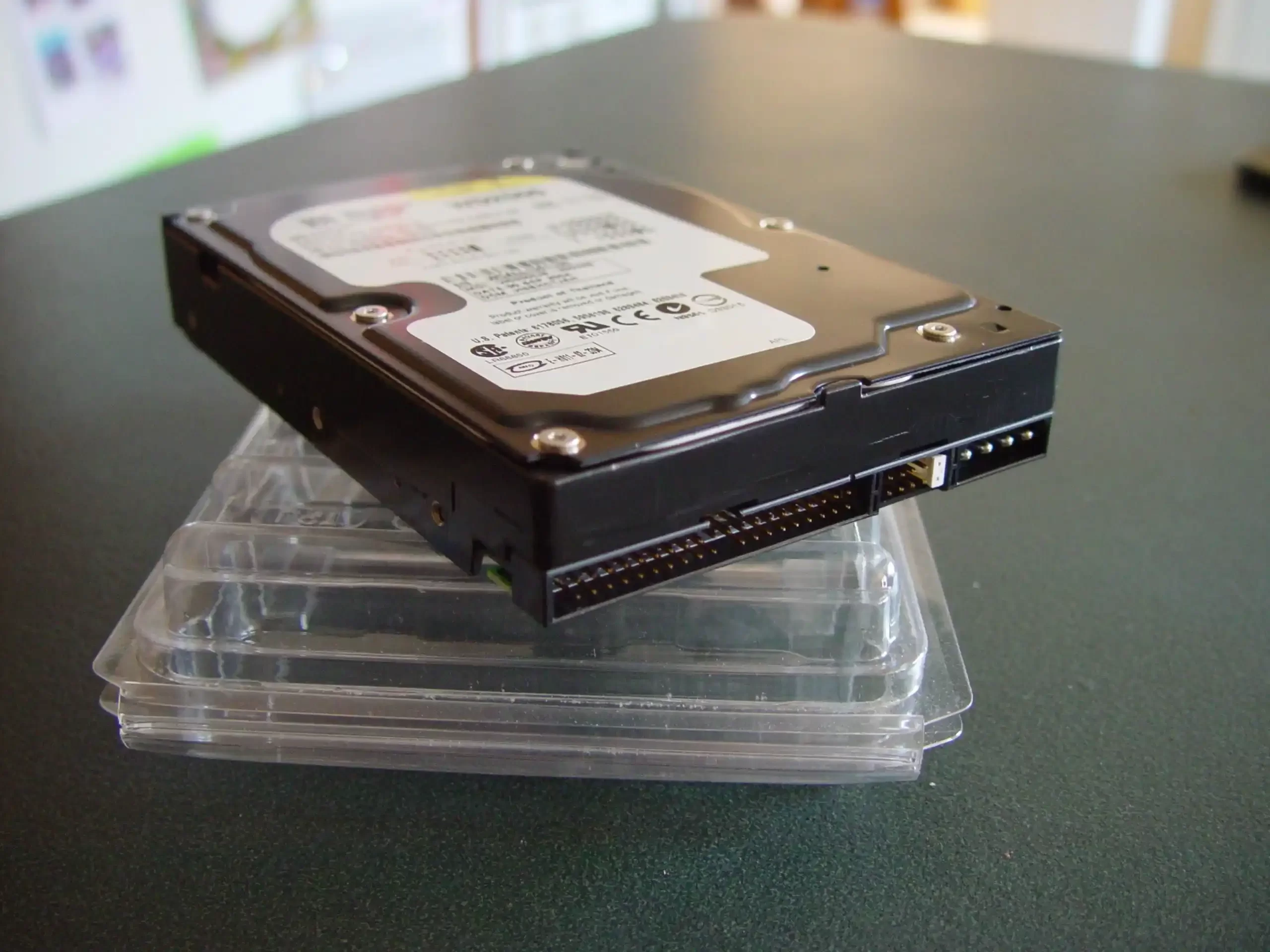
We learned the theory; now let’s move on to practice. Connecting a hard disk or optical drive to the system is very simple with the right sequence. But if you rush or apply brute force, you can break the pins.
You can also damage the solder joints on the PCB. Dealing with a motherboard repair for a broken port is not enjoyable. So stay calm and follow the steps.
First, cut all power to the system. Pulling the power cord from the outlet is best, because modern ATX motherboards provide standby voltage even when off.
Touch a metal surface to discharge static electricity. This small detail protects the delicate disk controller chips and EEPROMs.
Installing an IDE Hard Disk to the Motherboard: Molex Power Cable and Data Cable Connection
- Set the Jumper: Hold the disk in your hand. Look at the diagram on its label to set master, slave, or CS. If you’re installing a single disk, make sure it’s in the “Master” position.
- Plug the Data Cable into the Disk: Plug the black end of the 80-wire ribbon cable into the disk’s data port. The red stripe should be on the side facing the power input. It should seat with light pressure; don’t force it.
- Plug the Data Cable into the Motherboard: Plug the blue end of the cable into the primary IDE port on the motherboard. The motherboard usually says “IDE1” or “Primary IDE.”
- Connect the Molex Power: Plug the 4-pin Molex cable from the power supply into the disk. It’s almost impossible to plug this connector in backwards, because manufacturers have rounded the top and bottom corners.
- Arrange the Cables: Fold the ribbon cable neatly so it doesn’t block airflow. This also reduces signal interference.
After completing these steps, you can close the case and power on. If everything is correct, the motherboard BIOS automatically detects the disk at startup. You hear the disk sound. The spin of the spindle motor and the slight clicks of the actuator arm tell you that all is well.
IDE Disk Detection in BIOS, Boot Order, and Enhanced Mode Settings
BIOS configuration is just as critical as the hardware connection. Sometimes you install the disk correctly, but the BIOS has a disk detection problem. Don’t panic in this case. Apply the following checklist in order:
- Run Auto-Detect: Enter the “Standard CMOS Features” menu in the BIOS. Set the related channel to “Auto.” As the system restarts, it automatically reads the disk’s CHS and LBA information. If this doesn’t work, check your cable connections or the jumper.
- Set the Boot Sequence: Enter the “Advanced BIOS Features” menu. For boot priority, select your IDE disk as the “First Boot Device.” Especially if you’re installing the OS from CD-ROM, don’t forget to set the CD-ROM as the first device.
- Enhanced Mode and Legacy Mode Selection: In the chipset settings, you may see the “Enhanced Mode IDE” option. This mode runs legacy and SATA controllers together. If your OS is old (like Windows 98), choose “Legacy” or “Compatible” mode.
- 32 Bit Transfer and Block Mode: To boost performance, enable the “IDE HDD Block Mode” and “32 Bit Transfer Mode” settings. These settings activate DMA modes during data transfer. They also ensure efficient use of the drive buffer.
Proper BIOS configuration allows your disk to use its full potential. It also directly affects system stability and IOPS value.
Remember, the solution to the BIOS not detecting IDE disk issue often lies in these simple settings.
IDE vs SATA vs NVMe: Comparative Interface and Speed Analysis
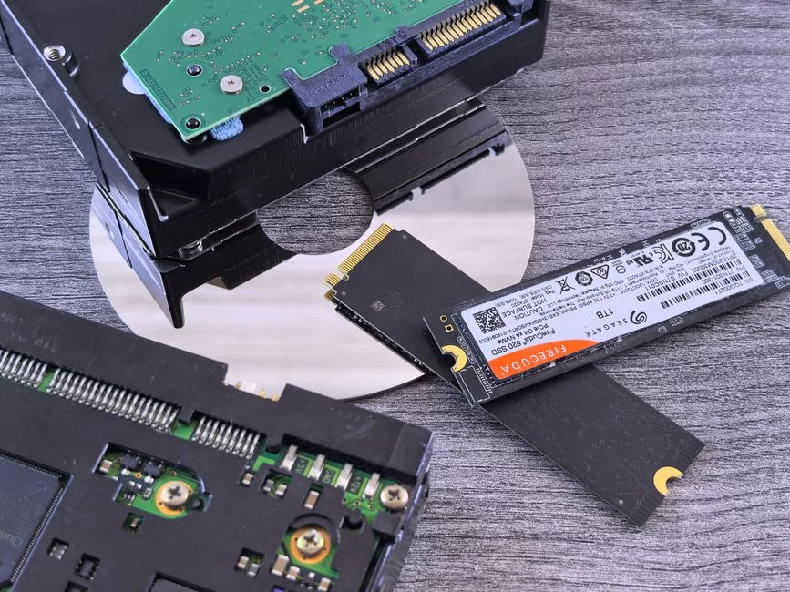
Technology doesn’t stand still; storage interfaces constantly evolve. This giant parallel interface first gave way to slim SATA cables. Then, NVMe M.2 drives, embedded directly on the motherboard, arrived.
This transition is not just a speed boost, but also an architectural revolution. For example, parallel data transmission struggled with synchronization issues. However, serial data transmission solved this problem at the root.
Modern NVMe drives use the multi-lane feature of the PCIe bus. This allows them to process gigabytes of data per second.
Difference Between IDE and SATA: Speed, Cable, and Practical Use
Comparing the IDE port and SATA is like a race between an elephant and a cheetah. The difference is not just speed, but also ease of use.
For example, this old standard’s cables were wide and blocked airflow. SATA cables, on the other hand, are slim and long. Also, SATA has no master-slave hassle. Each disk has its own cable and port.
Moreover, thanks to NCQ support, the system optimizes command queuing. This provides a big performance boost, especially in multitasking.
| Feature | IDE (PATA) | SATA |
|---|---|---|
| Data Transfer Rate (Max.) | 133 MB/s (ATA-7) | 600 MB/s (SATA III) |
| Cable Type | 40/80-wire wide ribbon | Thin, 7-pin serial cable |
| Maximum Cable Length | 18 in (official), 35 in (problematic) | 39 inches (1 m) |
| Devices per Port | 2 (Master/Slave) | 1 (Point-to-point) |
| Hot-Swap Support | No (does not officially support) | Yes |
| Jumper Setting | Required | Not Required |
| Command Queuing | None | Optimized with NCQ |
As you can clearly see, the answer to “Which is better, IDE or SATA?” is clear. For a modern system, SATA wins without question.
But this result does not reduce the value of the old standard. Especially in data recovery and retro hardware, this old interface is still king.
Hard Disk Speeds and ATA Versions: What Are ATA 100, ATA 133, and Ultra DMA 133?
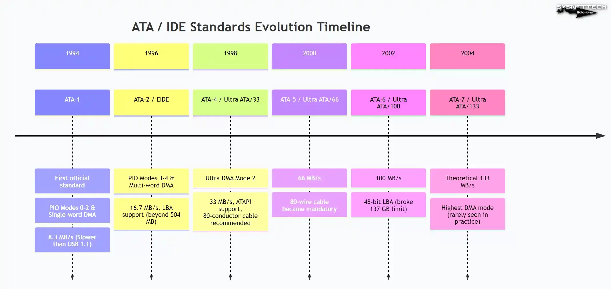
ATA standards document the evolution of this storage interface. Each new version pushed the limits of the previous one. Let’s take a look at the chronology of these speed monsters:
- ATA-1 (1994): It is the first official standard. It supports PIO modes 0-2 and single-word DMA. The maximum data transfer rate is 8.3 MB/s. It is even slower than today’s USB 1.1.
- ATA-2 / EIDE (1996): It brought faster PIO modes 3-4 and multi-word DMA. The speed rose to 16.7 MB/s. Also, it has LBA support for disks over 504 MB.
- ATA-4 / Ultra ATA/33 (1998): It reached 33 MB/s with Ultra DMA mode 2. ATAPI support for devices like CD-ROM matured in this version. At the same time, they began recommending the 80-conductor cable.
- ATA-5 / Ultra ATA/66 (2000): It doubled the speed to 66 MB/s. Using an 80-wire ribbon cable became mandatory for this speed. With the wrong cable, system speed drops or you get CRC errors.
- ATA-6 / Ultra ATA/100 (2002): It introduced the 100 MB/s speed limit. With 48-bit LBA, it surpassed the 137 GB capacity barrier. That’s why ATA 100 is the standard that paved the way for large disks.
- ATA-7 / Ultra ATA/133 (2004): It is the last major update of the parallel bus. The theoretical bandwidth is at the 133 MB/s level. So, what is Ultra DMA 133? It is the highest DMA mode the standard achieved. Moreover, seeing this speed in the real world is rare.
Knowing these versions helps you understand which motherboard will give an old disk full performance. For example, if you plug an ATA 133 disk into a Pentium II motherboard with ATA 33 support, the system will run slow. Fortunately, backward compatibility always exists.
Protocol Depth: PIO, DMA, ATAPI, and the Windows atapi.sys Driver
From the user’s perspective, you see only a cable. But behind the scenes, a complex data transfer protocol runs. This protocol determines how the processor dances with data. This dance has two basic figures: PIO and DMA.
Also, there is a software conductor managing this orchestra: the Windows atapi.sys driver. This driver translates logical block addresses into physical sector commands. Thus, it provides hardware abstraction.
In this section, we’ll look at what happens behind the curtain of your operating system. This information is very valuable, especially for troubleshooting performance issues. For example, if your disk runs very slowly, the cause may be that it’s stuck in PIO mode.
What Is the Difference Between PIO and DMA Modes?
PIO (Programmed Input/Output) is the oldest and simplest data transfer method. In this mode, the CPU personally steps in for every chunk of data to be read.
It’s like a chef carrying every plate by hand. This situation excessively occupies the CPU, especially during multitasking. As a result, your system stutters and slows down. PIO mode 4 theoretically offers 16.7 MB/s. But due to the CPU load, it practically falls far below this speed.
DMA (Direct Memory Access), on the other hand, is a major improvement. In this mode, a special controller (DMA controller) transfers data directly from the disk to memory. Meanwhile, the CPU is free to handle other tasks.
That means it can focus on other tasks. For this reason, enabling DMA is essential for system performance. Below, you see a head-to-head comparison of these two modes:
| Feature | PIO (Programmed I/O) | DMA (Direct Memory Access) |
|---|---|---|
| CPU Usage | Very High (Nearly 100%) | Low (Minimal intervention) |
| Data Transfer Rate | Low (PIO 4: 16.7 MB/s) | High (UDMA 6: 133 MB/s) |
| Multitasking Performance | Weak (System freezes) | Excellent (Runs in background) |
| Use Case | Old OSes, recovery environments | Modern OSes (Windows 2000 and up) |
| Data Integrity | CPU-controlled | Hardware-verified with CRC |
If you use Windows XP or an older system, check the DMA mode. You can do this from Device Manager.
Sometimes, the system repeatedly falls back to PIO mode due to CRC errors. In this case, deleting the driver and restarting reactivates DMA.
What Are CHS and LBA Addressing? The Role of the Windows atapi.sys Driver
The computer needs an addressing system to find a file on your disk. Initially, it used CHS addressing (Cylinder-Head-Sector).
This method exactly describes the physical geometry of the disk. It uses cylinder, head, and sector numbers. But this method hit a severe capacity limit of 504 MB. Modern operating systems have now completely left CHS behind.
To overcome this problem, engineers developed LBA addressing (Logical Block Addressing). This method abstracts the physical details. It gives each sector a simple sequence number. It’s like using a ZIP code instead of a home address.
This way, we reached 137 GB capacity with 28-bit LBA. With 48-bit LBA, petabytes of storage became possible.
To exceed the 137 GB LBA limit on old systems, users often used disk overlay software. Alternatively, they resorted to BIOS updates and disk capacity expansion methods.
Here, the Windows atapi.sys driver comes into play. This driver acts as a translator between the OS storage stack and the IDE controller. It converts incoming LBA commands into ATA commands the drive understands.
As a plus, it also handles optical drive connection and removable media management. If this driver fails or is outdated, your system can’t recognize large disks. Therefore, installing motherboard chipset drivers after Windows setup is essential.
Methods to Read and Convert IDE Disks Today
You have an aged, dusty magnetic disk drive in your hands. Maybe it came from a relative’s old computer. You’re curious about what’s inside.
With the right adapters and some patience, you can easily connect these drives to modern systems. During reading, details like sector size (512 bytes) and file system (FAT32, NTFS) become important.
Solutions range from a simple converter to a complex network storage unit. Which method you choose depends on your budget and technical skill.
Whether you use a simple USB converter or permanently connect the disk to your system, this guide will shed light on both cases.
Using Disks Externally with an IDE to USB Converter
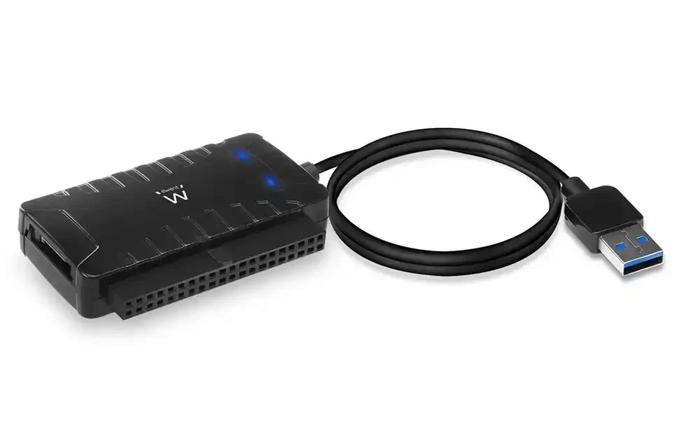
This method is by far the most practical and my most-used solution. An IDE to USB converter turns the disk into external storage. With just a few cable connections, you access the data in minutes.
My favorite device is the model carrying a JMicron IDE to USB chipset. This chip minimizes compatibility issues. It can also read SMART data.
- Choose the Right Adapter: For 3.5-inch desktop disks, a converter with an external power adapter is a must. The USB port cannot provide the 12V power the disk needs. But 2.5-inch laptop disks can usually be powered via USB.
- Check the Jumper: Before connecting the disk to the converter, make sure the jumper is in the “Master” or “Single” position. This setting is critical for USB converters.
- Power First, Then Data: First, give Molex power to the disk. Hear the spindle motor spin up. Then plug the IDE data cable into the converter. Finally, connect the USB cable to the computer.
- Open Disk Management: Run
diskmgmt.mscin Windows. The disk will appear here, but it may not have a drive letter assigned. Right-click and assign a letter or browse your data directly.
Using this IDE to USB 3.0 converter is the fastest way to read old disks. But remember, USB 2.0 converters are very slow for data transfer. Transferring hundreds of gigabytes over USB 2.0 is a true test of patience.
Connecting an IDE Disk to SATA or a Modern Motherboard via PCIe
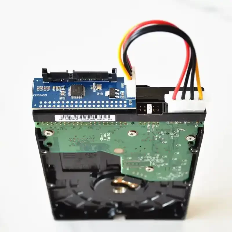
You may want to permanently connect the old disk to your system. There are two main ways to do this. The first and simplest is to use a bidirectional IDE to SATA adapter. You attach this small board to the back of the disk and connect SATA and power cables.
So, is an IDE-to-SATA adapter reliable? If it uses a quality chip (Marvell or JMicron), it is extremely reliable. But we often see data corruption and CRC errors with cheap adapters.
The second and more professional way is to use a PCIe IDE expansion card. If a modern motherboard has no PATA port, these cards are great. You plug it into a PCIe x1 slot and gain one or two channels.
The card usually carries a Promise or Silicon Image chip. Unlike USB converters, this method offers full support.
It fully handles SMART data, formatting commands, and bad sector scans. It is ideal for data recovery or sector repair. Also, if you have a truly old system, a PCI IDE controller card also works.
Another alternative is to put the disk in an external enclosure. An external IDE disk case makes the disk portable inside a sturdy shell. This method is very suitable for backup or transportation of the old disk.
However, IDE disk speeds and access time are low. Especially if you’re transferring over USB 2.0, the process can take a long time. Nevertheless, it is the least risky method for data recovery.
Connecting an Old IDE Disk to an Android Phone, Wi-Fi Network, and Building a Portable IDE NAS
We now carry supercomputers in our pockets. So, can we connect an old disk to these devices? Yes, if you’re wondering whether you can connect an IDE disk to a phone, the answer is an OTG connection.
But there’s a big hurdle here: power. Your phone cannot provide the 12V power to run a 3.5-inch disk. Therefore, you must use an adapter with an external power input.
Alternatively, only try with 2.5-inch laptop disks. You can mount the drive on Android with a mobile file manager. Then you can browse the files.
A more advanced scenario is building a portable IDE NAS. You connect an old but working disk to a router with a USB port.
For example, a Raspberry Pi or an OpenWRT device is perfect for this job. You connect the disk to the Pi with a converter, then set up a Samba server.
This gives you a network storage unit that all devices at home can access. This method turns the idea of reading an old disk via Wi-Fi into reality. It’s also a great step for e-waste prevention.
Some users search for a mobile data transfer app from an IDE disk. For example, they want to read the old disk with a phone and upload files directly to the cloud.
For this, a powerful OTG adapter and a file manager are enough. But in my experience, using a laptop for this job is more stable and faster. Especially for heavy tasks like bad sector scanning, mobile platforms fall short.
IDE Disk Data Recovery, Troubleshooting, and Advanced Configurations
These old magnetic drives are very prone to failure due to their mechanical nature. After years, when you power them on for the first time, the spindle motor may not spin. The actuator arm may get stuck or make strange noises.
Nevertheless, most of the time the problem is not physical but configuration-related. Now, we’ll cover the most common problems and their practical solutions. I will also explain how to overcome the capacity limits specific to this interface.
Remember, data recovery is a delicate job. A wrong move can cause you to lose data forever. Especially in a head crash situation, you scratch the magnetic platters. This makes data recovery impossible. Therefore, follow my advice carefully.
IDE Disk Not Working, Not Showing in Computer: Step-by-Step Solution
You turn on the system, but the BIOS doesn’t see the disk. Or you hear a clicking sound from the disk. This is the dreaded sound known as the “click of death.”
It usually points to an actuator arm that can’t return to the head parking area. Still, don’t lose hope right away. Here is my step-by-step troubleshooting guide, proven by experience:
- Listen to the Sounds: When you power the disk, do you hear the spindle motor spin? If there’s no sound at all, check the Molex power connector. Try another power cable. If you hear a clicking sound, the magnetic heads may be damaged or the servo pattern unreadable. In this case, professional help is essential.
- Isolate the Jumper and Cable: Connect the disk alone as master at the end of an 80-wire cable. Disconnect all other drives from the system. A faulty slave drive can make the master invisible too.
- Enter BIOS and Auto-Detect: Set the channel where the disk is connected to “Auto.” Save and exit. During POST, the system tries to detect the disk. If you see the model number, sector count, and capacity on the screen, your connection is solid.
- Test in Another System: Connect the disk to a different computer using a USB converter. If it doesn’t appear there either, the problem is most likely on the disk’s electronic board. We see IDE PCB failure often. Sometimes the firmware in the EEPROM gets corrupted.
- Troubleshoot Hardware Issues: If the disk works in another system, the problem is on your motherboard or BIOS settings. In this case, load “Load Optimized Defaults” and try again.
Physical Failure and Recovery Warning
These steps help you solve software-related problems. But in case of a physical failure, such as a head crash, never open the drive cover.
Even a single dust particle in a home environment can scratch the magnetic platters. This reduces your chance of data recovery to zero.
Overcoming the 137 GB LBA Limit, IDE RAID, and SCSI Comparison
The biggest obstacle in the history of this storage interface is the 28-bit LBA limit. This limit prevents you from seeing disks larger than 137 GB.
If you have an old Pentium 3 or Pentium 4 system, you can install a 160 GB disk. Then the BIOS shows only the 137 GB portion of this disk.
So, how do you bypass this limit? The cleanest solution is to update the motherboard BIOS. If the motherboard manufacturer added 48-bit LBA support, you solve the problem at the root. Otherwise, adding a modern controller with a PCI IDE controller card is the best solution.
Another advanced topic is IDE RAID configuration. Yes, you heard that right; you can also do RAID with this parallel interface.
You can use RAID cards with Promise or Highpoint chipsets. With these cards, you set up RAID 0 speed and RAID 1 security arrays.
This method is safe for backing up your data across multiple disks. But remember, if the RAID card fails, you can’t access your data until you find the same model card.
So, what do we see if we compare this technology to the corporate beast SCSI of that era? An IDE vs SCSI comparison is like racing a family sedan against a Formula 1 car.
SCSI is much faster and supports many more devices. It offers higher RPM values. It also has advanced features like NCQ (Native Command Queuing).
But its cost is just as high. That’s why IDE always won in personal computers. SCSI, on the other hand, remained indispensable in server rooms.
Is the IDE Port Still in Use Today? Retro Computing and Industrial Applications
We are in 2026, but this old motherboard port is not completely dead. Even though motherboard manufacturers no longer include it, the demand hasn’t ended.
So, is anyone still using the IDE port today? Absolutely yes, but in niche areas. For example, million-dollar CNC machines still run on old embedded systems with this interface. What’s more, thousands of retro gaming enthusiasts worldwide build original Windows 98 machines.
IDE technology is not just a nostalgic whim. Also, this technology is an important part of critical infrastructures.
From an e-waste prevention perspective, reusing these old disks is the best thing to do instead of throwing them away. In fact, disks in good condition find buyers for considerable prices in the second-hand market.
Retro PC Building: IDE Motherboard Selection and Storage Solutions
Building a retro computer is like creating a work of art. The most important part is choosing the right motherboard.
How do I choose an IDE motherboard for a retro computer? First, look at motherboards with classic chipsets like 440BX or i815. Prefer Slot 1 or Socket 370 models.
They show perfect compatibility with Windows 98 and MS-DOS games. You combine a Sound Blaster-compatible sound card and a Voodoo graphics card. Therefore, you get a classic machine.
On the storage side, you have two options. The first is to stay true to the original and use a spinning hard disk. But you never know when a 20-year-old disk will fail.
Therefore, the solution I strongly recommend is using a CF to IDE adapter. You insert a high-speed Compact Flash card into the adapter. You get completely silent and extremely reliable storage.
An SD to IDE adapter is a similar solution. But CF cards naturally work in PATA mode, so compatibility is better.
Even some advanced users connect industrial SSDs with these adapters. This way, they achieve extremely high speeds and high IOPS values.
When setting up these systems, finding BIOS updates and correct drivers is a big adventure. But in the end, the joy of playing on original hardware is worth everything. Similarly, this old port is indispensable for those repairing arcade machine hardware.
Industrial IDE Disk Backup and Sustainable Use
In factories or hospitals, there are machines that seem past their useful life but still run. The disks inside these machines are critically important.
That’s exactly where industrial IDE disk backup comes in. The goal is to take an exact sector copy of the disk without stopping the running system. I can list the following methods for this:
- Sector-Level Cloning: Use special disk cloning devices. These devices copy every sector of the disk independently of the operating system. Their ability to skip or repair bad sectors is vital.
- CF or SD Card Conversion: Remove the mechanical disk and insert a CF-IDE adapter in its place. This process completely eliminates moving parts. The machine runs for years unaffected by vibration and dust. Moreover, the MTBF (Mean Time Between Failures) value increases exponentially.
- Backup with USB Converter: If you can stop the machine, remove the disk and take its image with an IDE to USB converter. Store this raw disk image on a secure server or in the cloud.
The sustainable technology mindset teaches us to repurpose old hardware instead of trashing it. This is both economical and eco-friendly.
Believe me, thanks to these small adapters, multimillion-dollar machines continue to serve for many more years.
Resources to Understand the IDE Port More Deeply
The IDE port holds an important place in computer history. This section offers select resources to deepen the topic. Each provides information from a different perspective.
- Wikipedia – Parallel ATA: This article comprehensively covers the history, technical specifications, and operating principles of the IDE interface.
- Computer Hope – Integrated Drive Electronics Standard: Explains what IDE is, its working logic, and how it connects on the motherboard in current terms.
- GeeksforGeeks – PATA vs SATA Comparison: Presents a comparative overview of the main differences, speeds, and use cases between IDE and SATA.
- OSDev Wiki – PCI Controller Architecture: This technical wiki details the architecture and channel configuration of the IDE controller.
FAQ About IDE and PATA Technology
What are the physical differences between an IDE port and a SATA port?
What does the red stripe on an IDE cable indicate?
What is the Master and Slave jumper setting, and how do you do it?
What is the 137 GB LBA limit, and why does my old IDE disk show less capacity?
What should I pay attention to when buying an IDE to USB converter?
Can I connect my IDE disk to my Android phone?
Should an IDE cable be 40-pin or 80-wire? What is the difference?
What does the blue color on the IDE port mean?
What can I do at home to recover data from an IDE disk?
Are IDE and PATA the same thing?
Conclusion: The Place and Future of IDE Technology in Digital Heritage
If you’ve read this far, congratulations. You are now considered an expert on this old technology. As you’ve seen, the IDE standard is not just a connection type.
It is the silent hero of the democratization of the personal computer. Above all, with its cheap and easily integrable nature, it introduced millions of people to the digital world.
Today, it has taken on a new role: digital archaeology. We use this port to bring old photos, forgotten game saves, and historic software to the present.
This is a concrete bridge built between the past and the future. It is also still actively on duty in retro game console storage and industrial embedded systems.
What We Learned from IDE: The Evolution from Parallel to Serial Storage
This story showed us the ruthless but impressive evolution of technology. Wide parallel data buses gave way to high-speed serial lines, because as frequency increased in parallel, keeping bits in sync became impossible.
Serial communication solved this problem over a single line. It used the packet switching method. With NVMe M.2 storage, we reach distances measured in nanometers. We also achieve access times measured in microseconds.
But the core idea behind this revolution remained the same: to transfer data faster, cheaper, and more securely. Without that early vision, we wouldn’t have today’s compact and high-capacity devices.
So, the idea of integrating the controller into the drive electronics was very valuable. Understanding this legacy gives you the ability to look at the hardware world from a completely different window.
Evaluating Your Old Hardware and E-Waste Prevention Suggestions
Before throwing away that old disk sitting in your drawer, think again. There are many creative ways to repurpose it. Here are my favorite and most sustainable conversion ideas:
- Make It an External Backup Disk: Use it for your backups with an external enclosure or USB converter. It is still ideal for cold backups of non-critical data.
- Set Up a Network Drive (NAS): Share your disk across the whole house with an old Raspberry Pi or router. It’s perfect especially for a movie and music archive.
- Build a Retro Gaming Station: Plug this disk into an old PC and install FreeDOS or Windows 98 on it. Play classics like Doom and Quake on original hardware.
- Create Industrial Artwork: Open it up and make mirrors from the magnetic platters. You can build a knife holder from the strong neodymium magnets. This is a creative contribution to sustainable technology.
Remember, every old circuit board and every magnetic disk drive is a resource, not waste. If we give this storage technology the value it deserves, we continue to carry our digital heritage into the future. Now go and give those old disks the value they deserve!

Be the first to share your comment