
Today, networks are getting more and more linked. So, we need efficient routing protocols to handle network traffic. Mainly, RIP stands out. RIPv1 gives us a simple but helpful answer for smaller networks.
Knowing how to set up RIP is very important. This skill directly helps us make our network work better. It also makes talking between Routers smoother, which raises total network speed.
In this article, I will show the steps for configuring RIP (v1) on Cisco Routers using the GNS3 simulator. We will also take a very close look at the related dynamic routing protocol!
Understanding RIP (RIPv1) on a Cisco Router
RIP (Routing Information Protocol) is a system that finds paths on its own. So, we call it as Routing Information Protocol. It controls paths between Routers in a network. Also, it works by using a distance vector method.
It lets Routers talk about known and unknown networks. RIPv1 sends news of reachable places by often updating route lists.
It also shares the number of hops required to reach these destinations. This protocol is a good fit for smaller, simpler networks. So, it is an easy system because it is simple to use and set up.
However, it has limitations such as a maximum hop count of 15. This limit can block growth in bigger networks. Overall, RIPv1 works as a simple system for network routing. It allows good talking and path control between linked devices.
The RIP routing protocol broadcasts (255.255.255.255) between Routers. There are versions 1 and 2 of the RIP routing protocol. RIPv1 performs broadcast transmission. The other V2 version performs multicast transmission (224.0.0.9).
In our last article, we looked at the Routing Information Protocol. Now, we will turn on the RIPv1 system on the Routers in the GNS3 simulator.
How to Enable RIP on Routers with GNS3
Before you begin, open VMware Workstation. Then, make two Virtual Computers. Also, set the network options for these computers to get them ready for your practice space.
To summarize the relevant steps: first, create a VMnet in the VMware Virtual Network Editor. Then, integrate VMware virtual machines with GNS3. Finally, add Cloud to the workspace and make the necessary adjustments.
After that, follow these steps in order to enable RIP Version 1 (RIPv1) on the Routers.
1. Create a RIP Topology in GNS3
Step 1
As a first step, launch the GNS3 program and start a new project for RIPv1.

Step 2
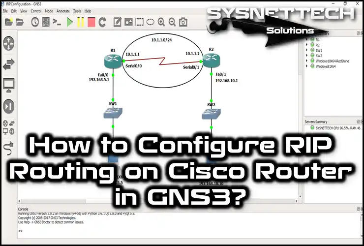
Please plan a network topology that shows the setup from the image. This plan must be made just for the RIPv1 Routing.
Validate that you show all elements the right way. Set up the Router, Switch, and links properly. So, you will make your network’s plan and job easier to see.

2. Add VMware VMs to the Topology
Step 1
Now, open your Windows 8.1 virtual PC in VMware. First, ensure that you have set VMnet1 as the network adapter. However, you can change this setting at any time. You can even easily create your own VMnet.
However, you must be careful at this step. Focus on the IP address block of the VMnets. Because this block forms the basis of your network, selecting the correct range guarantees the connection.

Step 2
Now, let’s move on to your Win10 virtual machine in VMware. Set the network adapter for this device to VMnet2. By choosing this, you will have turned on network isolation. This will let you make a proper link between different virtual networks.

Step 3
In the Virtual Network Editor program, the VMnet1 and VMnet2 IP address blocks are as follows.
After you set the TCP/IP settings for the virtual PCs, start them.

Step 4
The IP address of the first VM, which is a Windows 8.1 device, is 192.168.5.5/24.

Step 5
On the other hand, the Win10 machine also has an IP address of 192.168.10.10/24.

3. Configure Cisco Router Interfaces
Step 1
Up to this point, you have configured GNS3 & VMware settings for the RIP configuration. Now, configure the FastEthernet interface in the CLI command prompt of the Cisco Router R1.
Lastly, check all your links by doing the same steps for the Serial port.
R1#conf t
Enter configuration commands, one per line. End with CNTL/Z.
R1(config)#interface fastethernet 0/0
R1(config-if)#ip address 192.168.5.1 255.255.255.0
R1(config-if)#no shutdown
R1(config-if)#exit
R1(config)#interface serial 0/0
R1(config-if)#ip address 10.1.1.1 255.255.255.0
R1(config-if)#no shutdown
R1(config-if)#exit
R1(config)#do show ip int br
Interface IP-Address OK? Method Status Protocol
FastEthernet0/0 192.168.5.1 YES manual up up
Serial0/0 10.1.1.1 YES manual up up
FastEthernet0/1 unassigned YES unset administratively down down
Serial0/1 unassigned YES unset administratively down down
Step 2
In the same way, we set up the ports for the Cisco Router R2 like this:
R2#conf t
Enter configuration commands, one per line. End with CNTL/Z.
R2(config)#interface fastethernet 0/1
R2(config-if)#ip address 192.168.10.1 255.255.255.0
R2(config-if)#no shutdown
R2(config-if)#exit
R2(config)#interface serial 0/1
R2(config-if)#ip address 10.1.1.2 255.255.255.0
R2(config-if)#no shutdown
R2(config-if)#exit
R2(config)#do show ip int br
Interface IP-Address OK? Method Status Protocol
FastEthernet0/0 unassigned YES unset administratively down down
Serial0/0 unassigned YES unset administratively down down
FastEthernet0/1 192.168.10.1 YES manual up up
Serial0/1 10.1.1.2 YES manual up up
R2(config)#
4. Perform a Ping Test from the VMs to the Router
Step 1
You must check the link before setting the routing system. First, open a command box on your virtual computers. Right after, ping the Router ports they link to. This step checks the network communication, making a base for an easy setup.
Start a ping test from your Windows 8.1 virtual machine. First, target the R1 Router’s Fa0/0 interface. Then, repeat the same process for the Serial0/0 interface. In the end, both checks must work well. In short, you will prove that your connection is working correctly.

Step 2
Now, go to your Windows 10 guest OS and ping the interfaces of Router R2 connected here. This test will verify that your second network segment is also working. In other words, you will ensure that all your connections are active.

Step 3
Try pinging Serial 0/1 of Router R2 from Windows 8.1. We expect this test to fail. This is because we have not yet configured the Routers. So, because they do not know each other’s networks, they cannot talk.

Step 4
The ping check will also not work from the Windows 10 computer. As I said before, you cannot make a connection either way.

5. Enable RIP on the GNS3 Router
Step 1
Now, use the needed commands to turn on RIPv1 on Router R1’s command line. So, you start cross-network talk by beginning active routing.
R1#conf t
Enter configuration commands, one per line. End with CNTL/Z.
R1(config)#
R1(config)#router rip
R1(config-router)#network 10.1.1.0
R1(config-router)#network 192.168.5.0
R1(config-router)#end
R1#show ip route
Codes: C - connected, S - static, R - R-I-P, M - mobile, B - BGP
D - EIGRP, EX - EIGRP external, O - OSPF, IA - OSPF inter area
N1 - OSPF NSSA external type 1, N2 - OSPF NSSA external type 2
E1 - OSPF external type 1, E2 - OSPF external type 2
i - IS-IS, su - IS-IS summary, L1 - IS-IS level-1, L2 - IS-IS level-2
ia - IS-IS inter area, * - candidate default, U - per-user static route
o - ODR, P - periodic downloaded static route

Gateway of last resort is not set

C 192.168.5.0/24 is directly connected, FastEthernet0/0
10.0.0.0/24 is subnetted, 1 subnets
C 10.1.1.0 is directly connected, Serial0/0
R1#
Step 2
To perform the same process, switch to Router R2’s CLI. Here, apply the same command sequence. In short, you will enable the RIPv1 protocol on the second Router as well. That is, both Routers will begin learning each other’s networks.
R2#conf t
Enter configuration commands, one per line. End with CNTL/Z.
R2(config)#
R2(config)#router rip
R2(config-router)#network 10.1.1.0
R2(config-router)#network 192.168.10.0
R2(config-router)#end
R2#show ip route
Codes: C - connected, S - static, R - R-I-P, M - mobile, B - BGP
D - EIGRP, EX - EIGRP external, O - OSPF, IA - OSPF inter area
N1 - OSPF NSSA external type 1, N2 - OSPF NSSA external type 2
E1 - OSPF external type 1, E2 - OSPF external type 2
i - IS-IS, su - IS-IS summary, L1 - IS-IS level-1, L2 - IS-IS level-2
ia - IS-IS inter area, * - candidate default, U - per-user static route
o - ODR, P - periodic downloaded static route

Gateway of last resort is not set

C 192.168.10.0/24 is directly connected, FastEthernet0/1
R 192.168.5.0/24 [120/1] via 10.1.1.1, 00:00:04, Serial0/1
10.0.0.0/24 is subnetted, 1 subnets
C 10.1.1.0 is directly connected, Serial0/1
R2#
Step 3
You have now configured a RIPv1 Router on GNS3. Now, you can do a ping test from your VMs. For example, try accessing Windows 10 from Windows 8.1. Here, you will be able to complete the process successfully because the Routers now know the network paths.

Step 4
The ping operation will now be successful from your Windows 10 machine because you have enabled RIPv1. Routers are now sharing network news.

6. Verify RIPv1
Step 1
If routing is complete, type “show ip rip database” at the R1 command prompt. This command allows you to view all routing entries in the RIP database.
You can also view the metric values of the routes learned by your network devices. In short, the purpose of doing this is to verify the success of your configuration.

Step 2
Now repeat the same procedure on R2. Use the “show ip rip database” command. This will allow you to see the networks that R2 has learned.
You can also compare the logs of both Routers. Thus, you will confirm that your RIPv1 configuration is working symmetrically.

Step 3
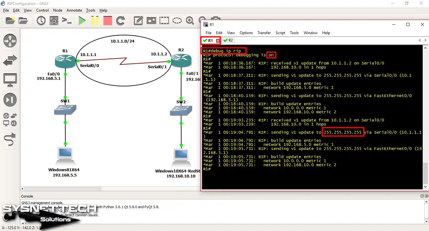
Now, switch to privileged configuration mode and run the “debug ip rip” command. With this command, you will see RIP Version 1 broadcast messages in real time. Here, you can study the traffic closely by watching network changes right away.
Step 4
As before, redo the same process on R2. This will allow you to monitor R2’s broadcast messages as well. To end, you see that both devices are talking correctly.

Show Commands Output for RIP Routing
- R1 RIP DB
- R2 RIP DB
- R1 RIP Debug
- R2 RIP Debug
- R1 RIP Route
- R2 RIP Route
- R1 Config
- R2 Config
R1#show ip rip dtbse
10.0.0.0/8 auto-summary
10.1.1.0/24 directly connected, Serial0/0
192.168.5.0/24 auto-summary
192.168.5.0/24 directly connected, FastEthernet0/0
192.168.10.0/24 auto-summary
192.168.10.0/24
[1] via 10.1.1.2, 00:00:20, Serial0/0
R1#
R2#show ip rip dtbse
10.0.0.0/8 auto-summary
10.1.1.0/24 directly connected, Serial0/1
192.168.5.0/24 auto-summary
192.168.5.0/24
[1] via 10.1.1.1, 00:00:02, Serial0/1
192.168.10.0/24 auto-summary
192.168.10.0/24 directly connected, FastEthernet0/1
R2#R1#debug ip rip
R-I-P protocol debugging is on
R1#
*Mar 1 00:18:36.167: R-I-P: received v1 update from 10.1.1.2 on Serial0/0
*Mar 1 00:18:36.167: 192.168.10.0 in 1 hops
R1#
*Mar 1 00:18:37.311: R-I-P: sending v1 update to 255.255.255.255 via Serial0/0 (10.1.1.1)
*Mar 1 00:18:37.311: build update entries
*Mar 1 00:18:37.311: network 192.168.5.0 metric 1
R1#
*Mar 1 00:18:40.159: R-I-P: sending v1 update to 255.255.255.255 via FastEthernet0/0 (192.168.5.1)
*Mar 1 00:18:40.159: R-I-P: build update entries
*Mar 1 00:18:40.159: network 10.0.0.0 metric 1
*Mar 1 00:18:40.159: network 192.168.10.0 metric 2
R1#
*Mar 1 00:19:03.235: R-I-P: received v1 update from 10.1.1.2 on Serial0/0
*Mar 1 00:19:03.239: 192.168.10.0 in 1 hops
R1#
*Mar 1 00:19:04.791: R-I-P: sending v1 update to 255.255.255.255 via Serial0/0 (10.1.1.1)
*Mar 1 00:19:04.791: build update entries
*Mar 1 00:19:04.791: network 192.168.5.0 metric 1
*Mar 1 00:19:05.731: R-I-P: sending v1 update to 255.255.255.255 via FastEthernet0/0 (192.168.5.1)
*Mar 1 00:19:05.731: R-I-P: build update entries
*Mar 1 00:19:05.731: network 10.0.0.0 metric 1R2#debug ip rip
R-I-P protocol debugging is on
R2#
*Mar 1 00:18:31.063: R-I-P: sending v1 update to 255.255.255.255 via Serial0/1 (10.1.1.2)
*Mar 1 00:18:31.063: R-I-P: build update entries
*Mar 1 00:18:31.063: network 192.168.10.0 metric 1
R2#
*Mar 1 00:18:32.107: R-I-P: received v1 update from 10.1.1.1 on Serial0/1
*Mar 1 00:18:32.107: 192.168.5.0 in 1 hops
R2#
*Mar 1 00:18:34.803: R-I-P: sending v1 update to 255.255.255.255 via FastEthernet0/1 (192.168.10.1)
*Mar 1 00:18:34.803: R-I-P: build update entries
*Mar 1 00:18:34.803: network 10.0.0.0 metric 1
*Mar 1 00:18:34.803: network 192.168.5.0 metric 2
R2#
*Mar 1 00:18:58.323: R-I-P: sending v1 update to 255.255.255.255 via Serial0/1 (10.1.1.2)
*Mar 1 00:18:58.323: R-I-P: build update entries
*Mar 1 00:18:58.323: network 192.168.10.0 metric 1
R2#
*Mar 1 00:18:59.911: R-I-P: received v1 update from 10.1.1.1 on Serial0/1
*Mar 1 00:18:59.911: 192.168.5.0 in 1 hops
R2#
*Mar 1 00:19:04.307: R-I-P: sending v1 update to 255.255.255.255 via FastEthernet0/1 (192.168.10.1)
*Mar 1 00:19:04.307: R-I-P: build update entries
*Mar 1 00:19:04.307: network 10.0.0.0 metric 1
*Mar 1 00:19:04.307: network 192.168.5.0 metric 2R1#show ip route rip
R 192.168.10.0/24 [120/1] via 10.1.1.2, 00:00:22, Serial0/0
R1#R2#show ip route rip
R 192.168.5.0/24 [120/1] via 10.1.1.1, 00:00:06, Serial0/1
R2#R1#show running-config
Building configuration...
Current configuration : 1091 bytes
!
version 12.4
service timestamps debug datetime msec
service timestamps log datetime msec
no service password-encryption
!
hostname R1
!
boot-start-marker
boot-end-marker
!
!
no aaa new-model
memory-size iomem 5
no ip icmp rate-limit unreachable
ip cef
!
!
no ip domain lookup
ip auth-proxy max-nodata-conns 3
ip admission max-nodata-conns 3
!
!
!
!
ip tcp synwait-time 5
!
!
interface FastEthernet0/0
ip address 192.168.5.1 255.255.255.0
duplex auto
speed auto
!
interface Serial0/0
ip address 10.1.1.1 255.255.255.0
clock rate 2000000
!
interface FastEthernet0/1
no ip address
shutdown
duplex auto
speed auto
!
interface Serial0/1
no ip address
shutdown
clock rate 2000000
!
router rip
network 10.0.0.0
network 192.168.5.0
!
ip forward-protocol nd
!
!
no ip http server
no ip http secure-server
!
no cdp log mismatch duplex
!
!
control-plane
!
!
line con 0
exec-timeout 0 0
privilege level 15
logging synchronous
line aux 0
exec-timeout 0 0
privilege level 15
logging synchronous
line vty 0 4
login
!
!
end
R1#R2#show running-config
Building configuration...
Current configuration : 1093 bytes
!
version 12.4
service timestamps debug datetime msec
service timestamps log datetime msec
no service password-encryption
!
hostname R2
!
boot-start-marker
boot-end-marker
!
!
no aaa new-model
memory-size iomem 5
no ip icmp rate-limit unreachable
ip cef
!
!
no ip domain lookup
ip auth-proxy max-nodata-conns 3
ip admission max-nodata-conns 3
!
!
ip tcp synwait-time 5
!
!
!
interface FastEthernet0/0
no ip address
shutdown
duplex auto
speed auto
!
interface Serial0/0
no ip address
shutdown
clock rate 2000000
!
interface FastEthernet0/1
ip address 192.168.10.1 255.255.255.0
duplex auto
speed auto
!
interface Serial0/1
ip address 10.1.1.2 255.255.255.0
clock rate 2000000
!
router rip
network 10.0.0.0
network 192.168.10.0
!
ip forward-protocol nd
!
!
no ip http server
no ip http secure-server
!
no cdp log mismatch duplex
!
control-plane
!
!
line con 0
exec-timeout 0 0
privilege level 15
logging synchronous
line aux 0
exec-timeout 0 0
privilege level 15
logging synchronous
line vty 0 4
login
!
end
R2#How to Enable RIPv1 with GNS3 ⇒ Video
You can also see our YouTube lesson on setting up RIPv1 on a Cisco Router. In this video, you will learn all the needed commands and how to set the protocol right.
Subscribe to our YouTube group for upcoming lessons and help us make good stuff!
Frequently Asked Questions (FAQ) About GNS3 RIPv1
- What do I need to configure RIP in GNS3?
- How can I check the RIP setup?
- How can I resolve common issues with RIPv1?
Conclusion
To sum up, setting up RIP (RIPv1) on Cisco Routers is key. I would say it is a needed skill for good network management. Really, this routing system works fully in smaller setups.
Understanding this, we can organize our networks for our needs. In other words, this system uses the distance vector method. Because of this, it can make good communication paths between devices.
You can simplify your configs by using the complete steps in our guide. This way, you better your network’s trust or speed. But, when using these settings, remember the limits of RIPv1!
For example, the maximum hop count may limit the network’s growth. However, RIP remains a practical choice for small networks. Plus, it works well in laboratory environments.
By learning what you need, you can overcome real network problems. You can make smoother interactions between your network devices.
As you learn more, I suggest you try advanced routing protocols. By doing so, you can further optimize your network’s potential.
As I mentioned, if you want to advance your networking skills, you should also look into RIPv2. This version has two great new features. The first is Variable Length Subnet Masks (VLSM). The second is multicast routing updates. For more information on this topic, check out our article on Configuring RIPv2 on a Cisco Router in GNS3.

Be the first to share your comment