
In this article, I will show you how to configure RIPv2 (RIP Version 2) on a Cisco Router using GNS3. First, I will list what you need to get the simulation world ready. This includes the required programs and their settings.
Next, we will examine the process of implementing RIP Version 2 step by step. First, we will see how the Routers are now, before we set up their network interfaces. Then, we will turn on the routing rules so the computers can talk. Additionally, we will check the routing table to make sure it is all done right.
We will also talk about real uses for RIP in networks with everyday examples. Plus, we will give you straightforward advice to fix frequent problems. In this detailed guide, we aim to help you better understand RIPv2.
RIPv2: Efficient Routing for Cisco Routers
First and foremost, RFC 2453 documents RIP Version 2 (RIPv2) in detail. This newer form does even better than the original RIP. One of the key features of RIPv2 is its use of Multicast. Specifically, it sends its updates to the special address 224.0.0.9.
This new multicast send cuts down on extra network load. Updates now go only to certain routers. Thus, not all devices in the broadcast domain receive them.
Additionally, it also works with Variable Length Subnet Masking (VLSM) & Classless Inter-Domain Routing (CIDR). These features let us use IP addresses in a better way.
With RIPv2, we can let different subnet groups talk well together. Because it makes routing paths better, we can also save IP addresses.
Also, RIPv2 needs less broadcast traffic. This helps stop network jams. This is very helpful when we use many local IP addresses.
In our previous articles, we explored the background by configuring RIP with GNS3. Now, I will show you how to set up RIPv2. This setup lets two Cisco Routers share many networks easily.
First, I will define the 192.168.5.0/24 network. Then, I will divide this network into two separate subnets. In short, we will connect different PCs in the subnets using RIPv2 routing.
Also, you can see our RIPv2 YouTube guide video about the ideas in this article.
How to Configure RIPv2 on Two Cisco Routers in GNS3
Before proceeding with the steps, review our “Using VPCS” guide. In this article, I will use VPCS (Virtual PC Simulator) for RIP configuration.
I can say that VPCS offers a more efficient approach compared to VMware virtual machines. In short, it replicates the functions of physical computers on the network. This allows us to set up quickly & test routing protocols.
With VPCS, you can simply make multiple nodes. Plus, you can set up network rules & observe RIPv2 actions. Truly, we eliminate the hassle of complex virtual machines.
1. Create a RIPv2 Network Topology
Step 1
Launch the GNS3 network tool to create a topology. Then, select the option to create a new project and name it “RIPv2.”
Now, pick an appropriate folder for the files in your project. Finally, when you open the project workspace, you are now ready to add devices and configure RIPv2.

Step 2
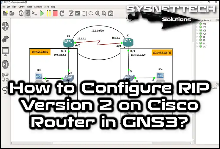
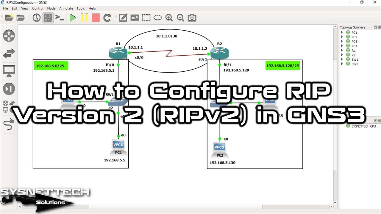
Now, design a detailed network topology for RIPv2 as shown in the image below. Add routers, switches, and four VPCs to your topology.
Also, add IP addresses and subnet masks for each interface. Then, separate the sections where you will perform RIPv2 routing.

2. Configure VPCSs
Step 1
First, you must set up the Virtual PC Simulator (VPCS) in your GNS3 workspace. So, ensure you link all VPCS devices to the correct network devices.
To help devices talk in the simulated environment, set the IP address for VPCS PC1.
PC1> ip 192.168.5.5/25 192.168.5.1
Checking for duplicate address...
PC1 : 192.168.5.5 255.255.255.128 gateway 192.168.5.1

PC1> show ip

NAME : PC1[1]
IP/MASK : 192.168.5.5/25
GATEWAY : 192.168.5.1
DNS :
MAC : 00:50:79:66:68:00
LPORT : 10014
RHOST:PORT : 127.0.0.1:10015
MTU: : 1500
PC1>
Step 2
In the same way, set up the IP details for VPCS PC2. After that, check that all the settings are correct.
PC2> ip 192.168.5.10/25 192.168.5.1
Checking for duplicate address...
PC1 : 192.168.5.10 255.255.255.128 gateway 192.168.5.1

PC2> show ip

NAME : PC2[1]
IP/MASK : 192.168.5.10/25
GATEWAY : 192.168.5.1
DNS :
MAC : 00:50:79:66:68:01
LPORT : 10016
RHOST:PORT : 127.0.0.1:10017
MTU: : 1500
PC2>
Step 3
When setting IPs for VPCS3, be very careful with the Subnet Mask. This is because you make sure devices can communicate when you split the network into parts.
PC3> ip 192.168.5.130/25 192.168.5.129
Checking for duplicate address...
PC1 : 192.168.5.130 255.255.255.128 gateway 192.168.5.129

PC3> show ip

NAME : PC3[1]
IP/MASK : 192.168.5.130/25
GATEWAY : 192.168.5.129
DNS :
MAC : 00:50:79:66:68:02
LPORT : 10018
RHOST:PORT : 127.0.0.1:10019
MTU: : 1500
PC3>
Step 4
Finally, set up VPCS4 exactly as the rules below say.
PC4> ip 192.168.5.135/25 192.168.5.129
Checking for duplicate address...
PC1 : 192.168.5.135 255.255.255.128 gateway 192.168.5.129

PC4> show ip

NAME : PC4[1]
IP/MASK : 192.168.5.135/25
GATEWAY : 192.168.5.129
DNS :
MAC : 00:50:79:66:68:03
LPORT : 10020
RHOST:PORT : 127.0.0.1:10021
MTU: : 1500
PC4>
3. Configure the Ports on the Cisco Router
Step 1
First, access the Command Line Interface (CLI) of the Cisco Router R1. Then, go to set up the FastEthernet 0/0 interface. Assign an IP address to this interface that is appropriate for your network scheme. Also, enable the port by adding the proper subnet mask.
Next, proceed to the Serial 0/0 interface. Here, also edit the relevant IP address and subnet mask. Be careful with these values because they must match your WAN connection. Also, remember to turn this port on so it can contact.
R1#conf t
Enter configuration commands, one per line. End with CNTL/Z.
R1(config)#interface fastethernet 0/0
R1(config-if)#ip address 192.168.5.1 255.255.255.128
R1(config-if)#no shutdown
R1(config-if)#exit
R1(config)#
*Mar 1 00:12:56.175: %LINK-3-UPDOWN: Interface FastEthernet0/0, changed state to up
*Mar 1 00:12:57.175: %LINEPROTO-5-UPDOWN: Line protocol on Interface FastEthernet0/0, changed state to up
R1(config)#
R1(config)#interface serial 0/0
R1(config-if)#ip address 10.1.1.1 255.255.255.252
R1(config-if)#no shutdown
R1(config-if)#end
R1#
You can verify the routing configuration by running the “show ip route” command on R1. This command shows you which active routes are working. In short, you can see the status of the network device’s ports.
R1#show ip interface brief
Interface IP-Address OK? Method Status Protocol
FastEthernet0/0 192.168.5.1 YES manual up up
Serial0/0 10.1.1.1 YES manual up up
FastEthernet0/1 unassigned YES unset administratively down down
Serial0/1 unassigned YES unset administratively down down
R1#
Step 2
In the same way, set up the ports for Router R2. Here, look closely at the subnet mask. This is key to splitting the network correctly.
R2#conf t
Enter configuration commands, one per line. End with CNTL/Z.
R2(config)#interface fastethernet 0/1
R2(config-if)#ip address 192.168.5.129 255.255.255.128
R2(config-if)#no shutdown
R2(config-if)#exit
R2(config)#
*Mar 1 00:14:49.607: %LINK-3-UPDOWN: Interface FastEthernet0/1, changed state to up
*Mar 1 00:14:50.607: %LINEPROTO-5-UPDOWN: Line protocol on Interface FastEthernet0/1, changed state to up
R2(config)#
R2(config)#interface serial 0/1
R2(config-if)#ip address 10.1.1.2 255.255.255.252
R2(config-if)#no shutdown
R2(config-if)#end
R2#
Check the interface configuration of Router R2. To do this, use the “show ip interface brief” command.
R2#show ip interface brief
Interface IP-Address OK? Method Status Protocol
FastEthernet0/0 unassigned YES unset administratively down down
Serial0/0 unassigned YES unset administratively down down
FastEthernet0/1 192.168.5.129 YES manual up up
Serial0/1 10.1.1.2 YES manual up up
R2#
Step 3
Before you turn on the routing, test the connections. To do this, perform a Ping test via the VPCSs.
Ping the Serial interface of Router R2 from VPCS PC1. This connection will fail because there is no suitable routing path between the two devices.

Step 4
The Ping result on VPCS PC3 is as follows. However, you will not be able to ping R1’s Serial interface from PC3.

4. Enable RIPv2 on the GNS3 Router
Step 1
To establish communication between two PCs in different locations, first access R1. Then, run the following command sequence. This will enable RIPv2. As a result, you will ensure data moves smoothly over the LAN.
R1#conf t
Enter configuration commands, one per line. End with CNTL/Z.
R1(config)#router rip
R1(config-router)#version 2
R1(config-router)#network 10.1.1.0
R1(config-router)#network 192.168.5.0
R1(config-router)#end
R1#
Step 2
Likewise, activate RIPv2 on R2. Then, set up the networks linked directly to the Router.
R2#conf t
Enter configuration commands, one per line. End with CNTL/Z.
R2(config)#router rip
R2(config-router)#version 2
R2(config-router)#network 10.1.1.0
R2(config-router)#network 192.168.5.128
R2(config-router)#end
R2#
Step 3
Now, test the connection by pinging from the VPCS PCs.
You will successfully ping the R2 Serial interface from PC1. This is because the two Routers now share connected networks.
As a result, your PC1 device will be able to access the 192.168.5.128/25 network successfully.

Step 4
Now, ping the other network from PC3 on the 192.168.5.128/25 network. You will see that this operation is successful.

5. Verify RIPv2 (RIP Version 2) in GNS3
Step 1
Display the routing table on Router R1 using the “show ip route” command.
Now, take a moment to look at the listed entries closely. These logs show the networks recognized by the Router. You can also learn about the ways it uses to reach these LANs.

Step 2
For similar results, type & enter the “show ip route” in R2. Then, check that you have all the routing details needed to study.

6. Review RIPv2 Messages
Step 1
Now, use the “debug ip rip” command on R2. This allows you to check the RIPv2 configuration. In short, you will see a log similar to the one in the image below.
In this image, you can see the RIPv2 routing updates. The protocol is sending the updates using the 224.0.0.9 multicast address.
Also, if you want to watch data moving between Cisco Routers, you can use Wireshark. So, this tool lets you study network data much better.

Step 2
Similarly, you can also check the RIPv2 records in R2. This lets you compare the details from each Router. In short, it also helps you confirm the network consistency.

Step 3
Now that everything is ready, let’s use Wireshark to verify RIPv2!
Right-click on the Serial connection between R1 & R2. Then, click on the “Start Capture” option. Now you can see how the routing rules protocol here.

Step 4
In the Packet Capture window, verify that the Link Type is Cisco DHLC. Immediately after, press OK to look at the RIP Version 2 details.

Step 5
When you start Wireshark, you will see RIP Version 2 packets as shown in the image below.
Please pay attention to the address 224.0.0.9 to better understand how it works. In short, RIPv2 transmits update packets between two Routers using a multicast address.

Show Commands for the RIPv2 Network
- R1#show running-config
- R2#show running-config
- R1#show ip rip dtbse
- R2#show ip rip dtbse
- R1#show ip route
- R2#show ip route
- R1#debug ip rip
- R2#debug ip rip
R1#show running-config
Building configuration...

Current configuration : 1106 bytes
!
version 12.4
service timestamps debug datetime msec
service timestamps log datetime msec
no service password-encryption
!
hostname R1
!
boot-start-marker
boot-end-marker
!
!
no aaa new-model
memory-size iomem 5
no ip icmp rate-limit unreachable
ip cef
!
!
!
no ip domain lookup
ip auth-proxy max-nodata-conns 3
ip admission max-nodata-conns 3
!
!
!
!
ip tcp synwait-time 5
!
!
!
interface FastEthernet0/0
ip address 192.168.5.1 255.255.255.128
duplex auto
speed auto
!
interface Serial0/0
ip address 10.1.1.1 255.255.255.252
clock rate 2000000
!
interface FastEthernet0/1
no ip address
shutdown
duplex auto
speed auto
!
interface Serial0/1
no ip address
shutdown
clock rate 2000000
!
router rip
version 2
network 10.0.0.0
network 192.168.5.0
!
ip forward-protocol nd
!
!
no ip http server
no ip http secure-server
!
no cdp log mismatch duplex
!
!
!
control-plane
!
!
!
line con 0
exec-timeout 0 0
privilege level 15
logging synchronous
line aux 0
exec-timeout 0 0
privilege level 15
logging synchronous
line vty 0 4
login
!
!
end
R1#
R2#show running-config
Building configuration...

Current configuration : 1108 bytes
!
version 12.4
service timestamps debug datetime msec
service timestamps log datetime msec
no service password-encryption
!
hostname R2
!
boot-start-marker
boot-end-marker
!
!
no aaa new-model
memory-size iomem 5
no ip icmp rate-limit unreachable
ip cef
!
!
!
no ip domain lookup
ip auth-proxy max-nodata-conns 3
ip admission max-nodata-conns 3
!
!
!
ip tcp synwait-time 5
!
!
interface FastEthernet0/0
no ip address
shutdown
duplex auto
speed auto
!
interface Serial0/0
no ip address
shutdown
clock rate 2000000
!
interface FastEthernet0/1
ip address 192.168.5.129 255.255.255.128
duplex auto
speed auto
!
interface Serial0/1
ip address 10.1.1.2 255.255.255.252
clock rate 2000000
!
router rip
version 2
network 10.0.0.0
network 192.168.5.0
!
ip forward-protocol nd
!
!
no ip http server
no ip http secure-server
!
no cdp log mismatch duplex
!
!
control-plane
!
!
!
!
line con 0
exec-timeout 0 0
privilege level 15
logging synchronous
line aux 0
exec-timeout 0 0
privilege level 15
logging synchronous
line vty 0 4
login
!
!
end
R2#
R1#show ip rip dtbse
10.0.0.0/8 auto-summary
10.1.1.0/30 directly connected, Serial0/0
192.168.5.0/24 auto-summary
192.168.5.0/24
[1] via 10.1.1.2, 00:00:22, Serial0/0
192.168.5.0/25 directly connected, FastEthernet0/0
R1#
R2#show ip rip dtbse
10.0.0.0/8 auto-summary
10.1.1.0/30 directly connected, Serial0/1
192.168.5.0/24 auto-summary
192.168.5.0/24
[1] via 10.1.1.1, 00:00:22, Serial0/1
192.168.5.128/25 directly connected, FastEthernet0/1
R2#
R1#show ip route
Codes: C - connected, S - static, R - RIP, M - mobile, B - BGP
D - EIGRP, EX - EIGRP external, O - OSPF, IA - OSPF inter area
N1 - OSPF NSSA external type 1, N2 - OSPF NSSA external type 2
E1 - OSPF external type 1, E2 - OSPF external type 2
i - IS-IS, su - IS-IS summary, L1 - IS-IS level-1, L2 - IS-IS level-2
ia - IS-IS inter area, * - candidate default, U - per-user static route
o - ODR, P - periodic downloaded static route

Gateway of last resort is not set

192.168.5.0/24 is variably subnetted, 2 subnets, 2 masks
C 192.168.5.0/25 is directly connected, FastEthernet0/0
R 192.168.5.0/24 [120/1] via 10.1.1.2, 00:00:00, Serial0/0
10.0.0.0/30 is subnetted, 1 subnets
C 10.1.1.0 is directly connected, Serial0/0
R1#
R2#show ip route
Codes: C - connected, S - static, R - RIP, M - mobile, B - BGP
D - EIGRP, EX - EIGRP external, O - OSPF, IA - OSPF inter area
N1 - OSPF NSSA external type 1, N2 - OSPF NSSA external type 2
E1 - OSPF external type 1, E2 - OSPF external type 2
i - IS-IS, su - IS-IS summary, L1 - IS-IS level-1, L2 - IS-IS level-2
ia - IS-IS inter area, * - candidate default, U - per-user static route
o - ODR, P - periodic downloaded static route

Gateway of last resort is not set

192.168.5.0/24 is variably subnetted, 2 subnets, 2 masks
R 192.168.5.0/24 [120/1] via 10.1.1.1, 00:00:07, Serial0/1
C 192.168.5.128/25 is directly connected, FastEthernet0/1
10.0.0.0/30 is subnetted, 1 subnets
C 10.1.1.0 is directly connected, Serial0/1
R2#
R1#debug ip rip
RIP protocol debugging is on
R1#
*Mar 1 00:24:22.779: RIP: sending v2 update to 224.0.0.9 via Serial0/0 (10.1.1.1)
*Mar 1 00:24:22.779: RIP: build update entries
*Mar 1 00:24:22.779: 192.168.5.0/24 via 0.0.0.0, metric 1, tag 0
R1#
*Mar 1 00:24:34.083: RIP: received v2 update from 10.1.1.2 on Serial0/0
*Mar 1 00:24:34.087: 192.168.5.0/24 via 0.0.0.0 in 1 hops
R1#
*Mar 1 00:24:36.891: RIP: sending v2 update to 224.0.0.9 via FastEthernet0/0 (192.168.5.1)
*Mar 1 00:24:36.891: RIP: build update entries
*Mar 1 00:24:36.891: 10.0.0.0/8 via 0.0.0.0, metric 1, tag 0
*Mar 1 00:24:36.891: 192.168.5.0/24 via 0.0.0.0, metric 2, tag 0
R1#
*Mar 1 00:24:48.759: RIP: sending v2 update to 224.0.0.9 via Serial0/0 (10.1.1.1)
*Mar 1 00:24:48.759: RIP: build update entries
*Mar 1 00:24:48.759: 192.168.5.0/24 via 0.0.0.0, metric 1, tag 0
R1#
R2#debug ip rip
RIP protocol debugging is on
R2#
*Mar 1 00:24:23.591: RIP: received v2 update from 10.1.1.1 on Serial0/1
*Mar 1 00:24:23.591: 192.168.5.0/24 via 0.0.0.0 in 1 hops
R2#
*Mar 1 00:24:33.427: RIP: sending v2 update to 224.0.0.9 via FastEthernet0/1 (192.168.5.129)
*Mar 1 00:24:33.427: RIP: build update entries
*Mar 1 00:24:33.427: 10.0.0.0/8 via 0.0.0.0, metric 1, tag 0
*Mar 1 00:24:33.427: 192.168.5.0/24 via 0.0.0.0, metric 2, tag 0
R2#
*Mar 1 00:24:34.803: RIP: sending v2 update to 224.0.0.9 via Serial0/1 (10.1.1.2)
*Mar 1 00:24:34.803: RIP: build update entries
*Mar 1 00:24:34.803: 192.168.5.0/24 via 0.0.0.0, metric 1, tag 0
R2#
How to Enable RIPv2 ⇒ Video
I suggest watching our YouTube guide video to set up RIPv2 well. First, you will learn the steps for setting up and checking, and see the whole method one part at a time.
Afterward, I kindly ask you to subscribe to our YouTube channel. This way, we will notify you about our new Cisco content. Your support is very valuable to us!
Frequently Asked Questions (FAQ) About GNS3 & RIPv2
- Why should I use GNS3 for RIP?
- What commands do you need to activate RIP Version 2?
- How can I be sure that RIPv2 is working correctly?
- What are some common problems I might encounter?
Conclusion
In this article, I explained how to subnet the 192.168.5.0/24 network. Specifically, I detailed the use of VLSM. Additionally, I showed how to set up the RIPv2 protocol configuration using GNS3.
Frankly, choosing RIPv2 is very important. Because RIPv1 does not support VLSM. Because of this, different subnets would have trouble talking. In other words, RIPv1 only recognizes classful routing. In summary, it would not provide flexibility for our network in this case.
We have enhanced routing updates using RIPv2 on the Cisco Router. Thus, we transmit subnet mask information as well.
In detail, we made sure all the network parts could talk easily. This lets us use the local addresses in the best way. On top of that, we also increased the routing between segments to work better.
If you want to keep learning about routing, please also see our guide on “Configuring OSPF in GNS3.” We explain OSPF, which is better than RIP, in that article. This active method works well with fixed setups. This way, you get much better at network testing.

Be the first to share your comment