
GNS3 network simulation is a strong tool that we all know and use a lot. I think that network workers and fans like it more than other tools. Also, you can connect it with VMware and VirtualBox virtual computers.
This lets you build complicated or true-to-life network layouts. In truth, this connection gives us endless new options. So, in this writing, we will link VMware VMs to GNS3 with a Cloud setup.
In summary, we can make your learning better by linking virtual setups. Also, we can do complete tests without using more physical computer parts. Because of this, you can easily build and test complex LAN designs.
The Easiest Way to Connect Your VMs in GNS3: Using the Cloud
The easiest way to add VMware or VirtualBox VMs is by using the Cloud shape. This makes a simple link between the virtual machines and GNS3. Because of this, you can build detailed network plans without using more real computers.
To make it work, set up a Cloud node in GNS3. Then, connect it to your virtual machine’s interface card. This step means picking the right network connections. Make sure that both the emulator and your VMs can talk to each other.
By using the bridging tool, you can make your network tests bigger. You can also add real physical devices. This makes your learning much better with true-to-life LAN setups.
When GNS3 gets newer, it becomes easier to use. This gives you a simpler and faster way to work. This emulator software lets people test virtual PCs well. It helps make real-looking network plans that act like actual situations.
Before, older GNS3 had a “Host” choice. This choice lets people connect VMware with GNS3. But now, this task is a lot easier. The new Cloud Nodes tool in version 2.0 makes things better for users.
In our guide, I will show you how to add virtual computers to the topology. On the other hand, I will use both GNS3 and VMware Workstation.
These steps will lead you through the setup job one after the other. Therefore, you can create a detailed virtual network area.
How to Connect VMs to the Topology via Cloud on GNS3
To set up your cloud, first make two virtual computers. I suggest using the VMware program for this.
After you make your virtual PCs, do the steps below. So, these steps will help you use the cloud with no problems.
1. Add a Node to the GNS3 Topology
Step 1
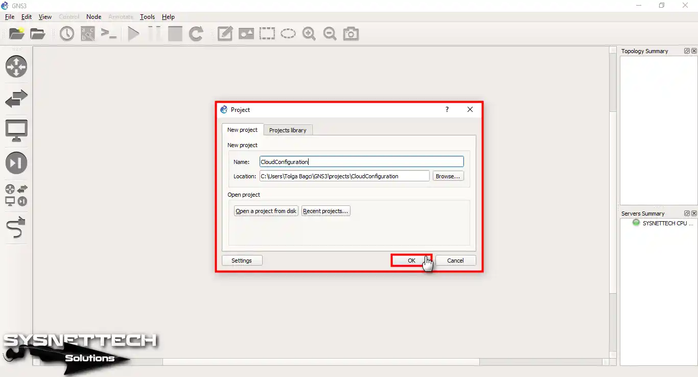
Regardless of the circumstances, our first task in GNS3 is to start with a new project. Because of this, start your network testing program, type a name in the Project box you see, and press OK.
Step 2
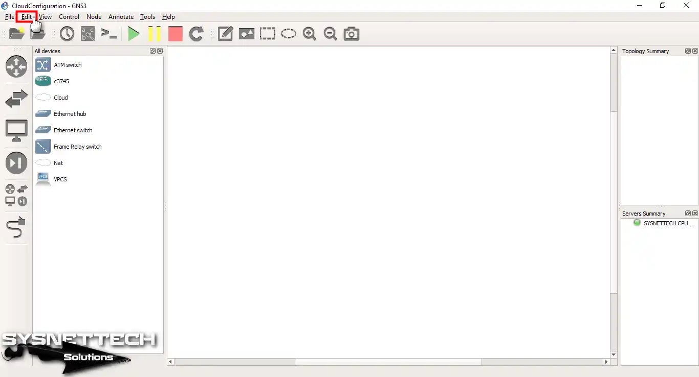
To add a cloud, first click Edit in the menu.
Step 3
Press on Edit, then pick Preferences and go on.

Step 4
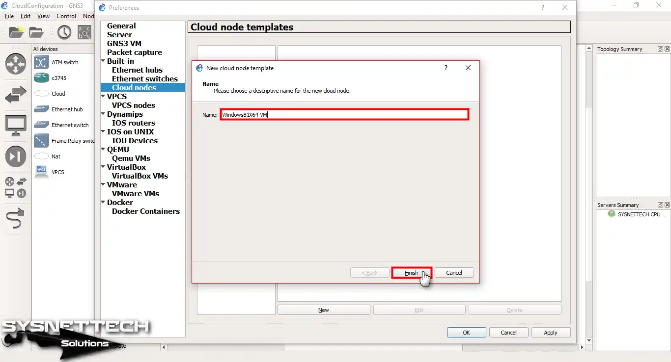
Now, select “Cloud nodes” from the settings as shown in the image below, then click the New button.
This is the first step in creating a new Cloud template.

Step 5
When you make a cloud node, you will, of course, link it to the virtual machines you plan to deploy.
Therefore, it is key to type the name of your virtual system. This will decide the possible space and jobs for your programs.

Step 6
For example, I am writing Windows8x64-VM here. I suggest you write the name of your own VM.
2. Configure the Cloud PC’s Adapter
Step 1
So far, we’ve actually created a GNS3 Cloud PC. Now, let’s set up the card by pressing Edit in the Templates box.

Step 2
In the image below, you need to add an interface to the Cloud device. First, create an Ethernet interface on the Host. Then, connect this interface to the Cloud.
Open the VMware Virtual Network tool and put in the VMnets you made. To do this, press the “Show special Ethernet interfaces” choice. That is, this lets you see your special network links.

Step 3
You must select VMnet for the Windows 8 VM. Therefore, click the down arrow next to the Ethernet option.

Step 4
Here, add the “VMware Network Adapter VMnet1” that you have configured.

3. Change the Cloud Icon to a PC
Step 1
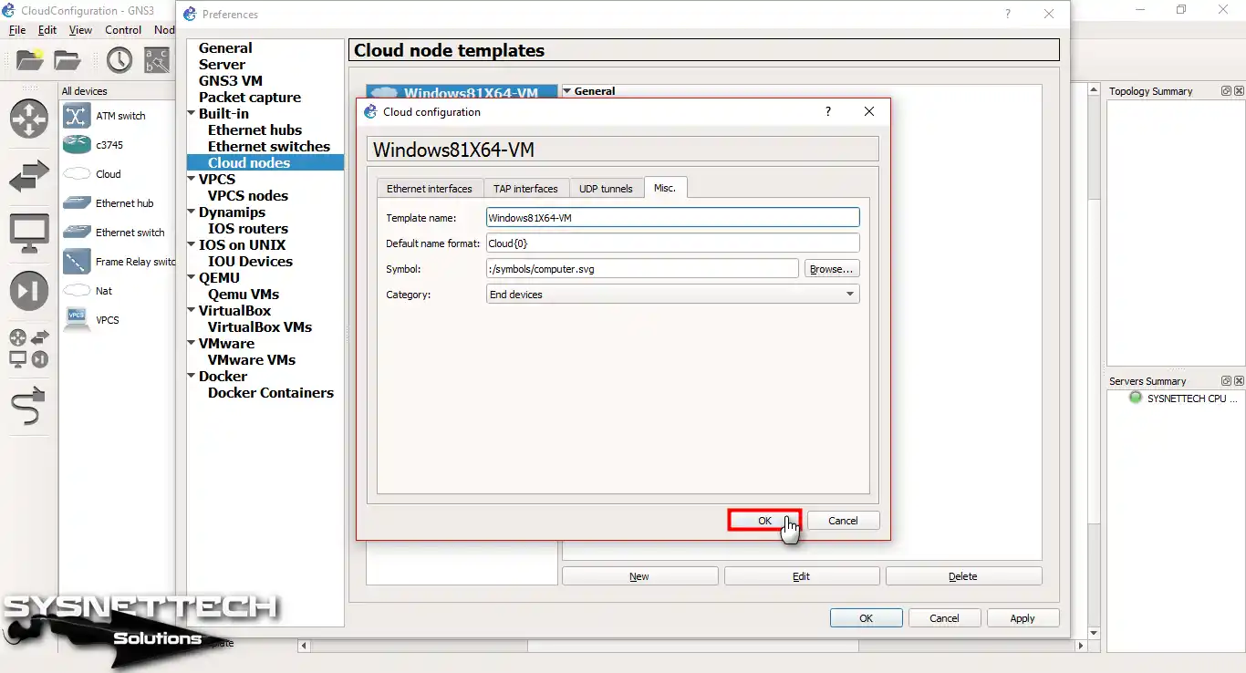
First, select the Cloud icon in your workspace. Then, click on the Misc. tab. Next, change the icon to Computer.

Step 2
You can see that the default value for the Symbol tag is “cloud.svg”. Now, click Browse to replace this symbol with one from your PC.

Step 3
You can see the choices you have on the Symbol Selection screen. Based on how you are planning your work, you can change this feature on GNS3 to fit what you like.
Therefore, scroll down a bit, select Computer, and click OK.

Step 4
You can now check here that you have changed the Symbol value. Then, go forward by pressing OK to keep your new settings.
Step 5
Now, start adding a new Cloud node for the Windows 10 guest machine again.

Step 6
In the same way, go on by typing the Cloud name for the VM you put in.

Step 7
Just like you did before, select VMnet2 for Windows 10. Of course, change its icon to make your topology more organized.

Step 8
Now, let’s create a small network design in the GNS3 program. After that, let’s test our Cloud PCs.

Step 9
As you can see, we now have two Cloud devices in the All Devices section!

4. Configure the VMnets of Virtual PCs
Step 1
Finally, let’s look at the Network Adapter settings for our VMware virtual PCs! If you examine the image below, you can see that I set the VMnets to Host-Only in the VNE tool.
I selected VMnet1 as the custom for Windows 8.1.

Step 2
I also selected VMnet2 for our other machine, the Windows 10 VM.

Step 3
Before running VMs, check your host PC’s network settings as follows. First, verify the VMnet1 & VMnet2 configuration from Network Connection Settings on your physical PC. In short, configure the settings as shown below, as I did.
So, why are we changing the IP addresses of the VMnets? In truth, we often use .1 IP numbers as the default gateway. Therefore, I changed these addresses to avoid conflicts.
If you ignore this, you may encounter network errors in your GNS3 topologies.

5. Add Cloud PCs to the GNS3 Topology
Step 1
First, create a GNS3 network topology like the one below. Then, add your Cloud node computers to your workspace.
Pick the Cloud1 tool from the devices, but change its hostname to help keep things in order.
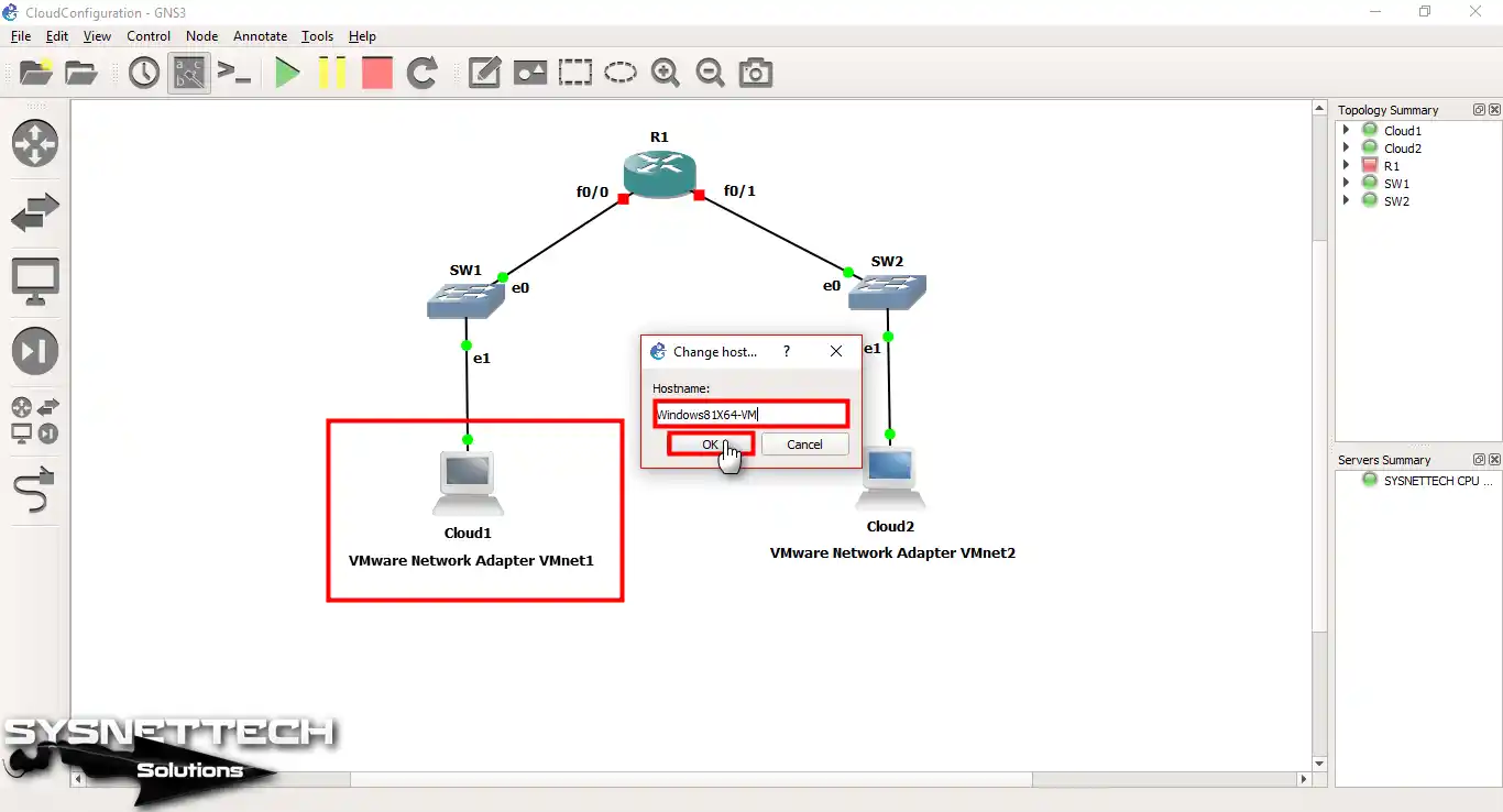
Step 2
I have also named Cloud2 for Windows 10. Because of this, go on by setting up its hostname.

Step 3
As a last step, press the green start button to run all tools in your GNS3 work. Then, go on to set up because the Cisco Router’s FastEthernet ports are on.

Step 4
First, open the CLI command prompt for GNS3 Router R1. Here, you must assign an IP address to the FastEthernet0/0 interface. Finally, repeat the same process for the Fa0/1 interface.
R1#conf t
Enter configuration commands, one per line. End with CNTL/Z.
R1(config)#interface fastethernet 0/0
R1(config-if)#ip address 192.168.5.1 255.255.255.0
R1(config-if)#no shutdown
R1(config-if)#exit
R1(config)#
*Mar 1 00:02:19.999: %LINK-3-UPDOWN: Interface FastEthernet0/0, changed state to up
*Mar 1 00:02:20.999: %LINEPROTO-5-UPDOWN: Line protocol on Interface FastEthernet0/0, changed state to up
R1(config)#interface fastethernet 0/1
R1(config-if)#ip address 192.168.10.1 255.255.255.0
R1(config-if)#no shutdown
R1(config-if)#end
R1#
Step 5
Because I changed the VMware adapters, I must set the IP numbers myself. Therefore, let’s set the TCP/IP values for the Windows 8 VM to 192.168.5.0/24.

Step 6
Similarly, I am setting up the IP addresses of my Windows 10 virtual computer for the 192.168.10.0/24 network.

Step 7
Now that I’ve taken care of everything, I’m testing the network connection by pinging from Win8.1 to Win10.

Step 8
Now, ping from Win10 to Win8.1. As you will find by checking your network link, your two virtual PCs are talking well. In truth, I can say that the Cisco Router makes this talk.

Show Commands for the Router in Cloud Configuration
- R1#show running-config
- R1#show ip route
- R1#show ip route connected
R1#show running-config
Building configuration...
Current configuration : 1043 bytes
!
version 12.4
service timestamps debug datetime msec
service timestamps log datetime msec
no service password-encryption
!
hostname R1
!
boot-start-marker
boot-end-marker
!
!
no aaa new-model
memory-size iomem 5
no ip icmp rate-limit unreachable
ip cef
!
!
no ip domain lookup
ip auth-proxy max-nodata-conns 3
ip admission max-nodata-conns 3
!
!
ip tcp synwait-time 5
!
!
interface FastEthernet0/0
ip address 192.168.5.1 255.255.255.0
duplex auto
speed auto
!
interface Serial0/0
no ip address
shutdown
clock rate 2000000
!
interface FastEthernet0/1
ip address 192.168.10.1 255.255.255.0
duplex auto
speed auto
!
interface Serial0/1
no ip address
shutdown
clock rate 2000000
!
ip forward-protocol nd
!
!
no ip http server
no ip http secure-server
!
no cdp log mismatch duplex
!
!
control-plane
!
!
line con 0
exec-timeout 0 0
privilege level 15
logging synchronous
line aux 0
exec-timeout 0 0
privilege level 15
logging synchronous
line vty 0 4
login
!
!
end
R1#
R1#show ip route
Codes: C - connected, S - static, R - RIP, M - mobile, B - BGP
D - EIGRP, EX - EIGRP external, O - OSPF, IA - OSPF inter area
N1 - OSPF NSSA external type 1, N2 - OSPF NSSA external type 2
E1 - OSPF external type 1, E2 - OSPF external type 2
i - IS-IS, su - IS-IS summary, L1 - IS-IS level-1, L2 - IS-IS level-2
ia - IS-IS inter area, * - candidate default, U - per-user static route
o - ODR, P - periodic downloaded static route

Gateway of last resort is not set

C 192.168.10.0/24 is directly connected, FastEthernet0/1
C 192.168.5.0/24 is directly connected, FastEthernet0/0
R1#
R1#show ip route connected
C 192.168.10.0/24 is directly connected, FastEthernet0/1
C 192.168.5.0/24 is directly connected, FastEthernet0/0
R1#
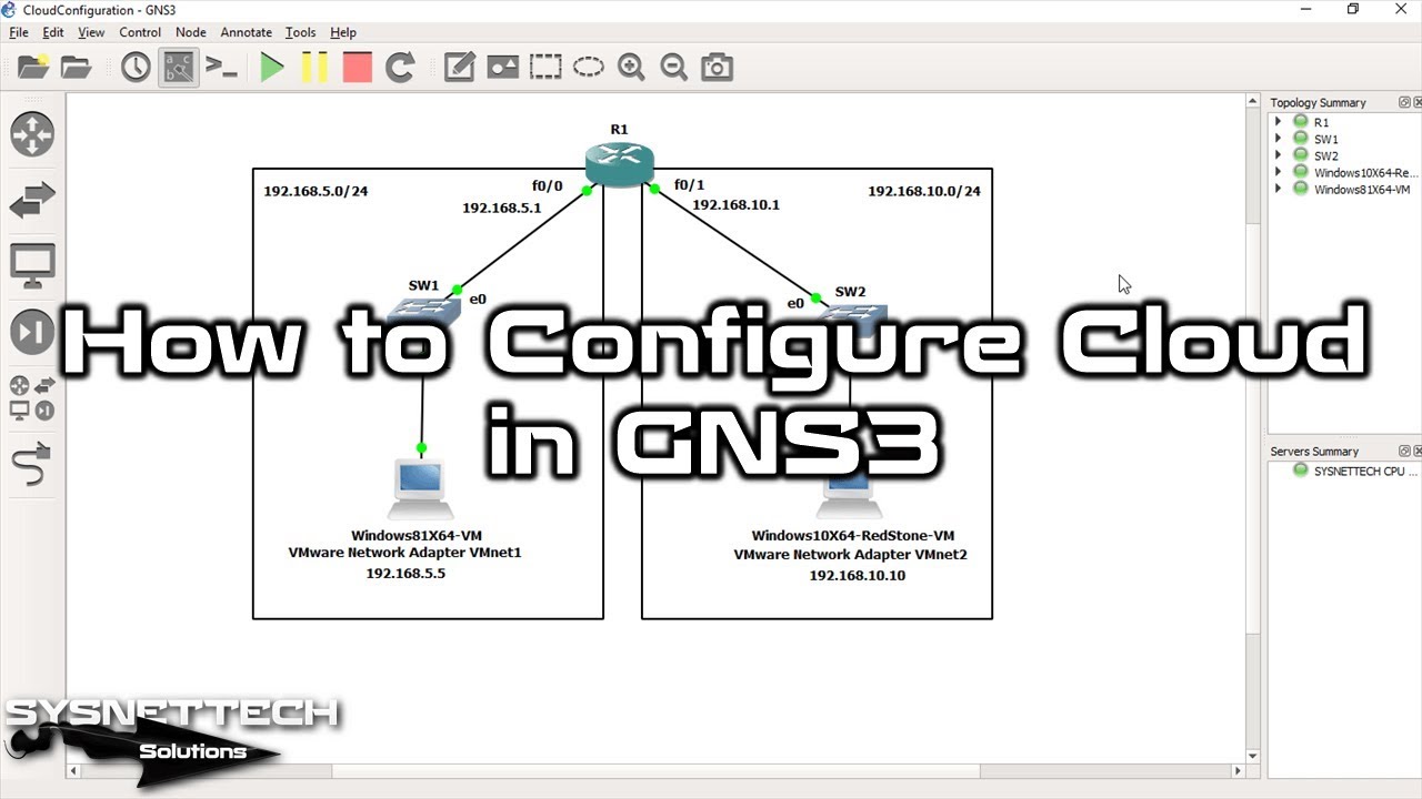
How to Use Cloud Nodes in GNS3 ⇒ Video
See our lesson video to learn how to add your virtual computer to GNS3. We also ask you to join our YouTube group. This lets you see our newest lesson videos. By doing this, you will be helping our work.
Frequently Asked Questions (FAQ) About Cloud Nodes
- What is Cloud in GNS3?
- How do I add a cloud device?
- Which network interfaces can I use for the cloud?
- Can I use multiple nodes in a single GNS3 project?
- How can I connect my GNS3 devices to an external network?
Conclusion
In short, you can add your VMware virtual computers to GNS3 through the Cloud. Also, this connection is perfect for network testing and trying.
Also, you can build detailed LAN setups. You do not need genuine computer parts. Because of this, this answer is excellent for both study and job tasks.
By doing the steps I have shown, you can easily set up your virtual systems. Also, you can do complete network checks and grow what you know.
This emulator app always makes using it better. Tools like Cloud nodes, most of all, make this easier. This lets you go further with your web plans. In the end, you will move fast toward new network answers.
Additionally, you can use VPCS instead of VMs. This allows you to run your network simulations faster, saving you time. To do this, you can read our VPCS Configuration guide in GNS3. So, this will make your end device testing skills better.
Also, check out our article on How to Configure Loopback Adapter in GNS3. You can create a virtual LAN card on routers without using any virtual PCs. This way, you won’t need to add anything else to your topology.

1 Reader Comment
I did everything that you said to do, but I cannot ping from my router to my VM. I can ping my default gateways router from my VM though. I’m not sure whats going on? I’m using vmware workstation pro 16 and the latest GNS3