
The GNS3 software, which we use to enhance our knowledge of computer networks, also supports Layer 3 Switch devices. In the always-changing world of networks, we often use L3 switches to ensure data travels well between our devices. So, we provide efficient data transmission and communication among devices in our environment.
To prepare for tests from Cisco or other companies, we use advanced network tools using GNS3. Also, if we like networking, we try to improve. In this article, we’ll examine why we use GNS3 Layer 3 switches in the emulator program and how we set them up.
Advantages of Using Layer 3 Switches in GNS3
A Layer 3 Switch (L3 Switch) is a unique network tool that works on the third level of the OSI model, known as the network layer. In comparison, Layer 2 Switches work on the second layer and send frames based on MAC addresses. The big plus of L3 over L2 is that it uses IP addresses to figure out where to send things. That’s why people like using Layer 3 devices in big and complicated networks.
A big plus of having a Layer 3 Switch in the network is that it can handle different groups of IP addresses (called subnets) and VLANs. These devices look at their IP addresses to figure out where to send incoming packets. Then, they find the best way to get the packages to where they’re going, making the network faster and more responsive.
If you’re getting ready for Cisco exams, you’re probably using the GNS3 emulator app. With this make-believe program, you can also play around with Layer 3 Switch devices. It lets you copy real network devices on your computer in a virtual world. When you add a Router or Switch, you can make your network projects better and do some really cool setups.
The best thing about using an L3 device with GNS3 is that we don’t need actual equipment. These network devices cost a lot of money, so buying them might not be possible. However, with great software like GNS3, we can use these devices on our computers in a virtual environment.
What Can We Do with L3 Switch in the GNS3 Program?
This software lets us emulate a Cisco L3 Switch device, and that gives us a bunch of good things. First off, we can use it on our computer without having to buy a real one. Plus, we can use almost everything that an actual device can do, like all the cool features and commands.
For instance, with L3 devices, we can control where users can and cannot go using something called Access Control Lists (ACLs). In simple terms, we can stop a user from doing things like pinging with the ICMP protocol. L3 devices also have cool extras like Quality of Service (QoS). This helps network administrators set up priorities for how traffic moves around the network.
Another big reason we like using L3 devices is because of something called VLANs (Virtual Local Area Networks). With VLANs, we can split one physical setup into different make-believe groups. This helps us keep devices and computers logically apart in the network. To send data between these pretend networks, we use something called Inter-VLAN.
Also, we can use special rules called routing protocols like OSPF, EIGRP, RIP, or BGP. In short, they help us set up a network that can change and adapt more quickly.
Layer 3 switches can do something called Virtual Router Redundancy Protocol (VRRP) and Hot Standby Router Protocol (HSRP). When we use a Layer 3 Switch in the GNS3 program, it helps make sure our network stays working even if something goes wrong.
The things an L3 switch can do in GNS3 aren’t just these. It can also work with Network Address Translation (NAT) and Intrusion Detection Systems (IDS).
How to Add a Layer 3 Switch (L3 Switch) on GNS3
Installing an L3 Switch in GNS3 is similar to installing a Cisco Router. So, you can use it to perform switching-based operations in the simulator.
When you put this device into GNS3, you can do things like VLAN, 802.1Q Trunking, and InterVLAN Routing.
First of all, click the button below to download the IOS image for your Cisco Layer 3 Switch to your computer.
Once you get the IOS image for the L3 switch on your computer, open up the network simulator and do the steps below.
Steps:
Step 1
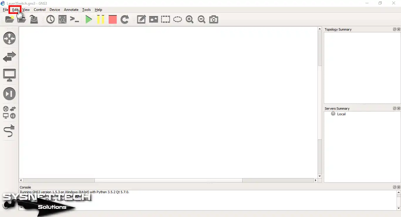
To add a new device to the system, start by choosing the Edit option in the GNS3 GUI.
Step 2
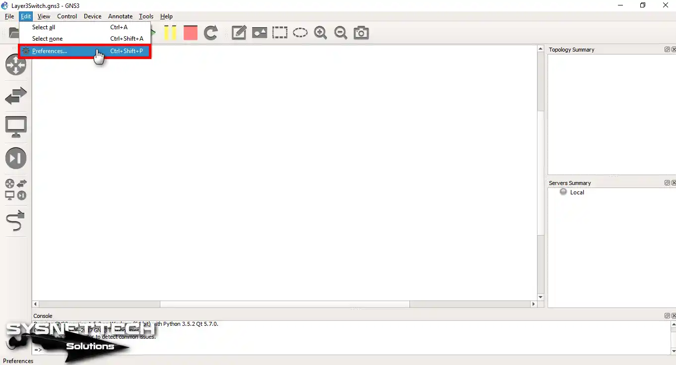
Inside the Edit menu, click on Preferences. This is where you can access and set settings up just the way you like them.
Step 3
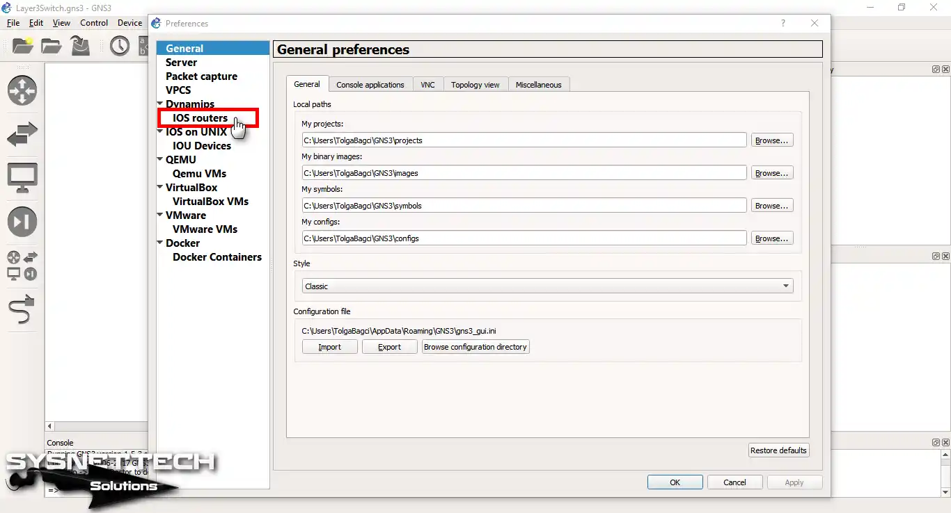
Look for and click the IOS Routers tab in the General Preferences window. In short, this is where you handle routers that use the IOS system.
Step 4
If you remember, we had added an L2 Switch from Qemu VMs before. Now, click the New button in the IOS Router templates window to add the L3 Switch.

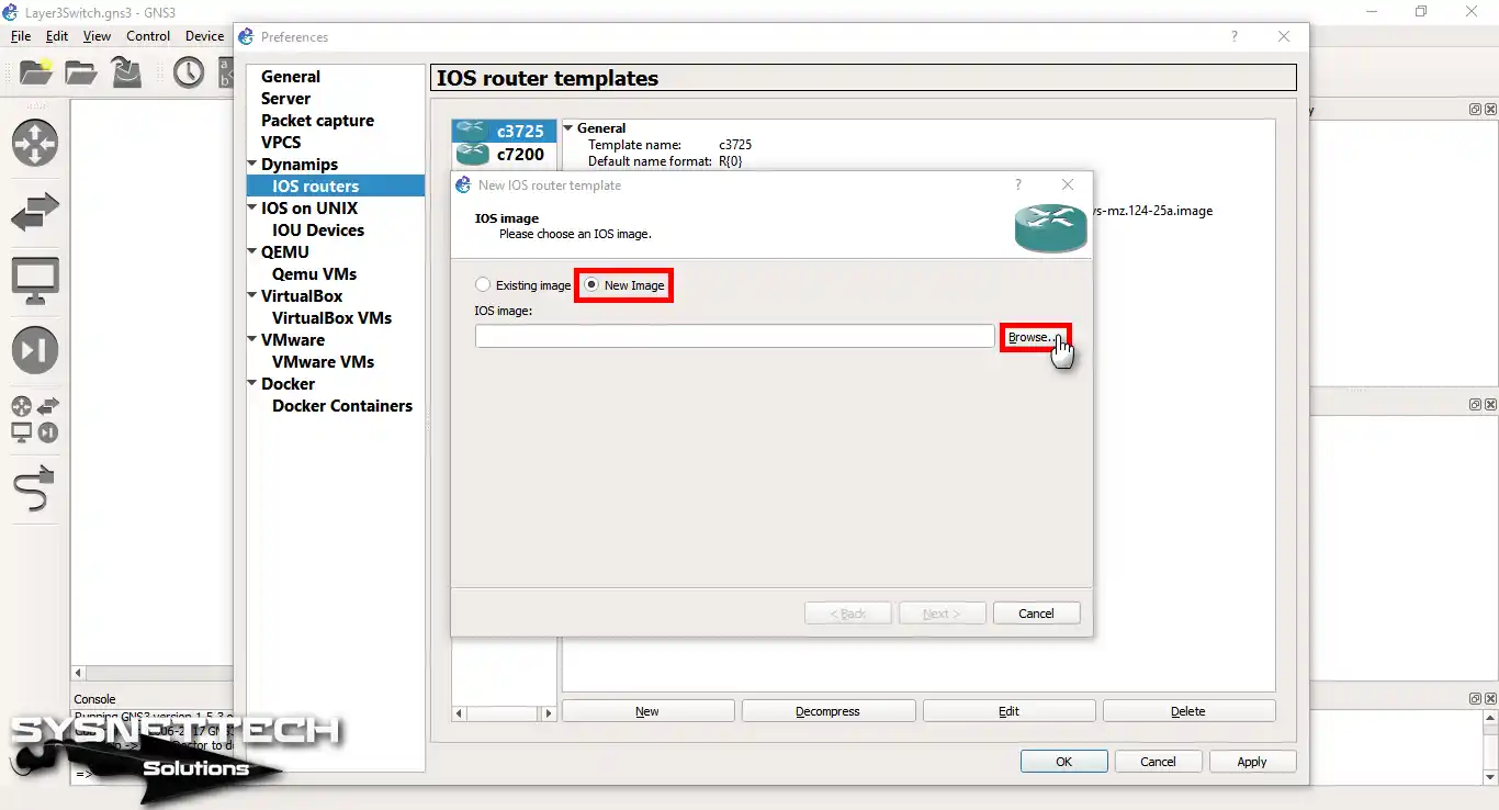
Step 5
In the IOS Image window, start by choosing New Image. Then, click Browse to select the image for the IOS system from your files.
Step 6
Choose the IOS version you downloaded by clicking the button mentioned. After that, click Open to begin adding the chosen iOS version to GNS3.

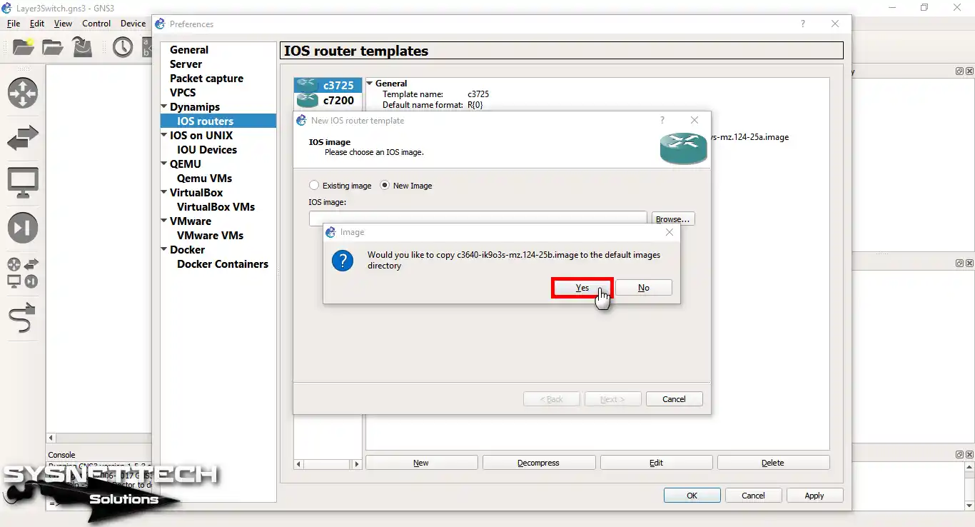
Step 7
When GNS3 asks, say Yes to copy the IOS to the image folder.
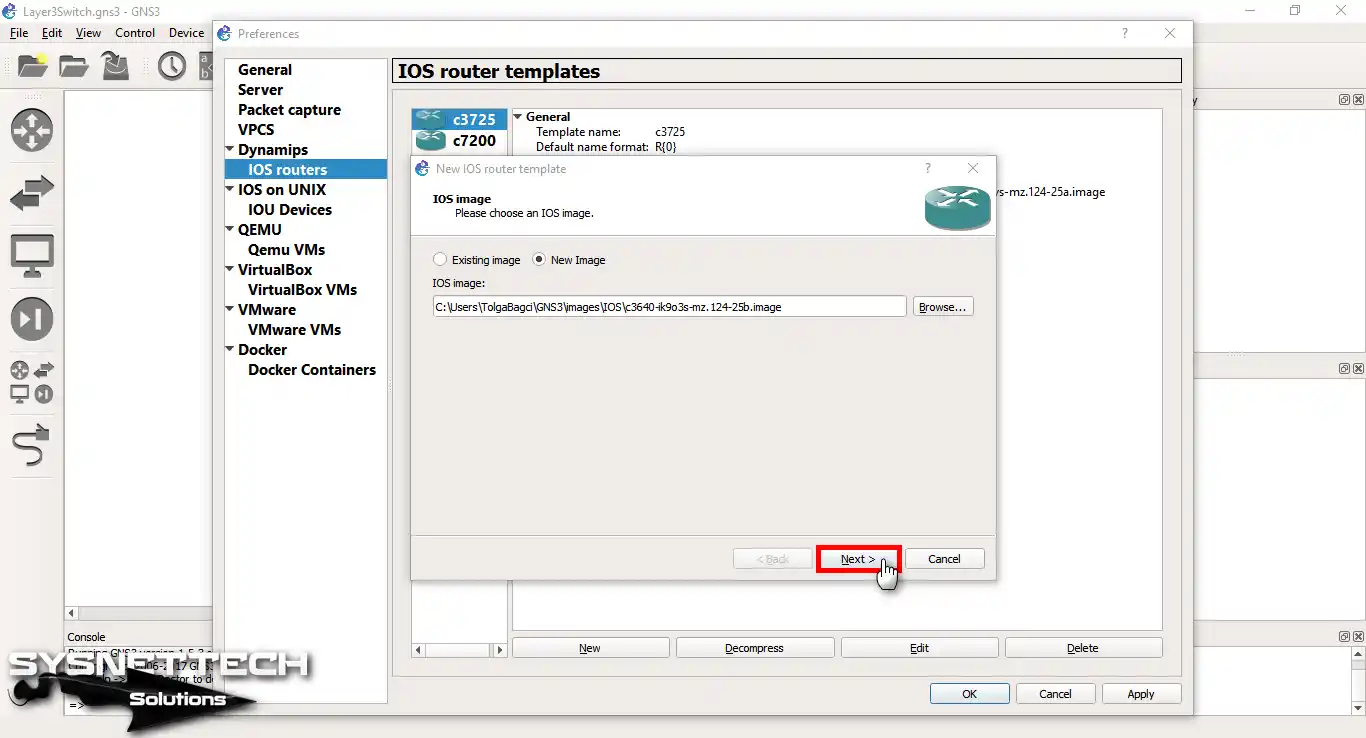
Step 8
Once you’ve added the Switch IOS successfully, go to the next step by clicking Next. Then, move to the next part to keep going with the configuration or setup process.
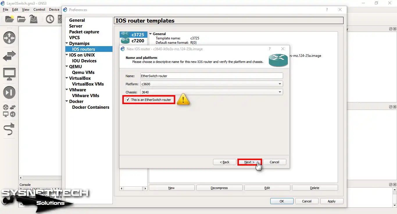
Step 9
In this step, choose This is an EtherSwitch Router, and then click Next.
Step 10
Keep the RAM value for the Layer 3 Switch as it is, and then click Next.

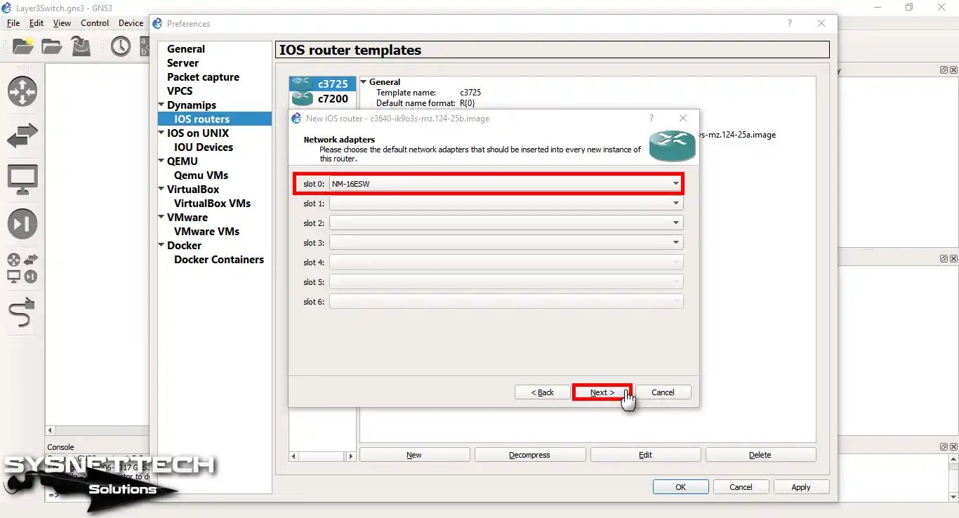
Step 11
Choose the NM-16ESW in Slot 0 in the Network Adapters.
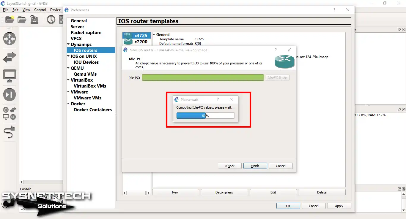
Step 12
Click on the Idle-PC Finder button to make your Layer 3 Switch IOS work better. In short, it figures out the best value for it to work well.

Step 13
Wait a moment as the system figures out the Idle-PC value. This step is crucial to make sure your system works well and uses resources effectively. In short, this step helps find the best settings for your system. So, your patience here helps make sure the system works as smoothly as possible.
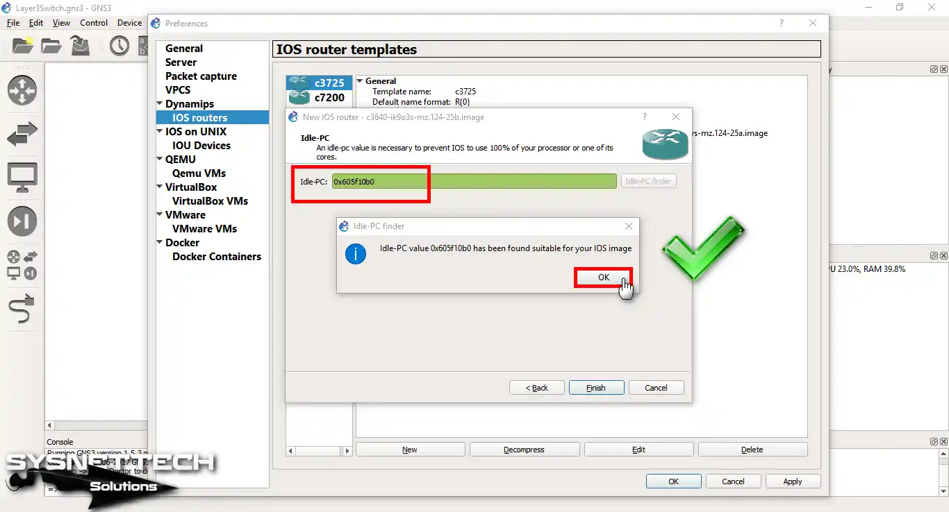
Step 14
Once you figure out the best Idle-PC value, click OK to move forward. So, this makes sure the IOS system works at its best.
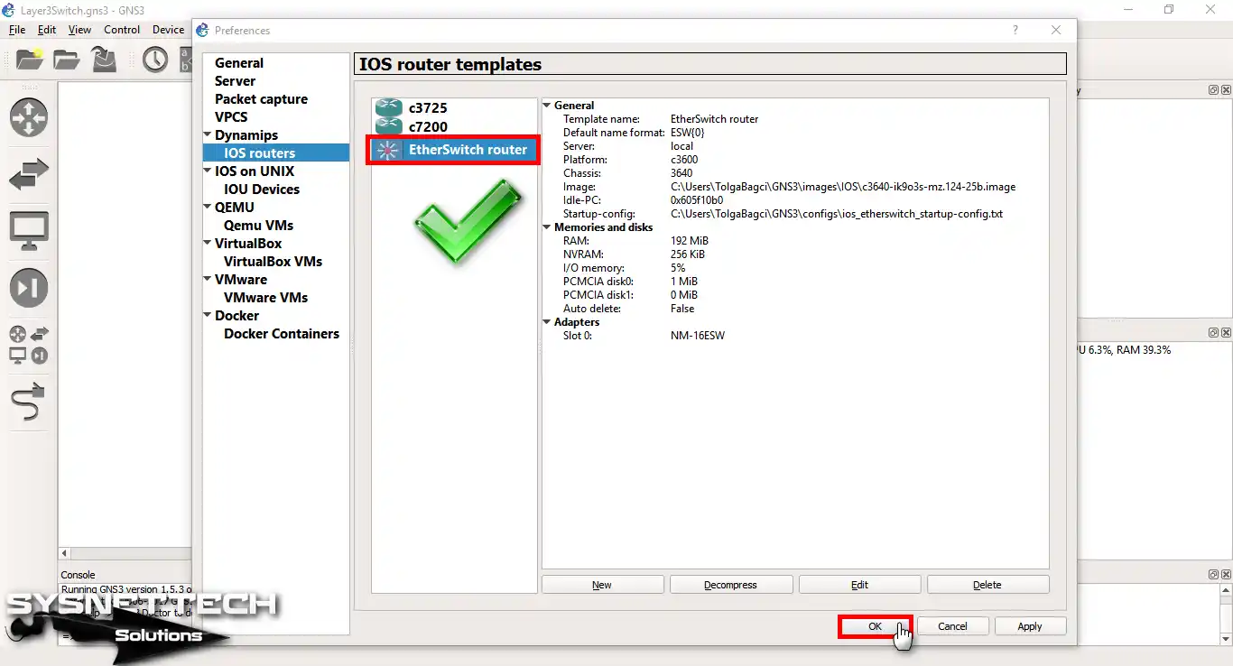
Step 15
The image below tells us that we added the Layer 3 Switch (EtherSwitch Router) successfully.
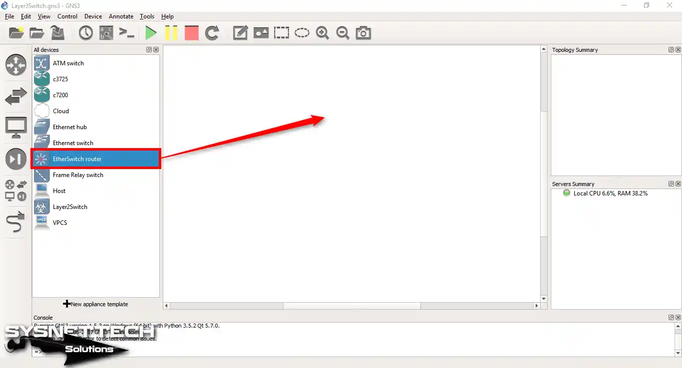
Step 16
Start by dragging the Layer 3 Switch onto GNS3. So, drop it on the workspace to begin setting it up.
Step 17
Please create a topology as follows: then, double-click on the L3 switch.

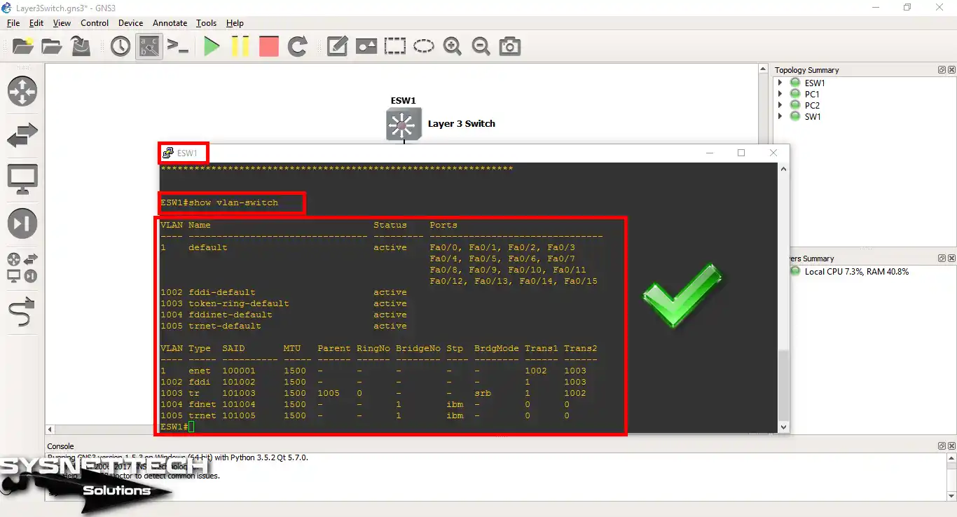
Step 18
To check the Switch, type the show vlan-switch command in the command interface (CLI).
Set up the Switch by typing in the following commands.
ESW1# conf t
ESW1(config)#interface vlan 1
ESW1(config-if)#ip address 192.168.10.1 255.255.255.0
ESW1(config-if)#no shutdown
ESW1(config-if)#exit
ESW1(config)#infterface fastethernet0/0
ESW1(config-if)#no shutdown
ESW1(config-if)#exit
ESW1(config)#exit
ESW1#
Step 19
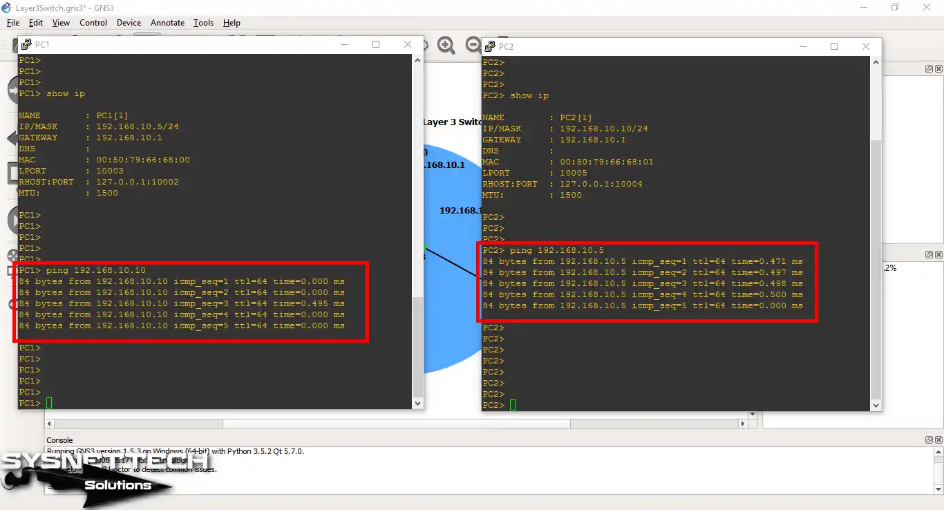
Set up the VPCS and check the connection by pinging the VLAN1 interface.

Step 20
The VPCS can ping each other without any problems.
Show Commands:
1. show running-config
ESW1#show running-config
Building configuration...
Current configuration : 2035 bytes
!
version 12.4
service timestamps debug datetime msec
service timestamps log datetime msec
no service password-encryption
no service dhcp
!
hostname ESW1
!
boot-start-marker
boot-end-marker
!
!
no aaa new-model
memory-size iomem 5
no ip routing
no ip icmp rate-limit unreachable
!
!
no ip cef
no ip domain lookup
!
!
ip auth-proxy max-nodata-conns 3
ip admission max-nodata-conns 3
!
!
vtp file nvram:vlan.dat
!
!
ip tcp synwait-time 5
!
!
!
interface FastEthernet0/0
description *** Unused for Layer2 EtherSwitch ***
!
interface FastEthernet0/1
description *** Unused for Layer2 EtherSwitch ***
shutdown
!
interface FastEthernet0/2
!
interface FastEthernet0/3
!
interface FastEthernet0/4
!
interface FastEthernet0/5
!
interface FastEthernet0/6
!
interface FastEthernet0/7
!
interface FastEthernet0/8
!
interface FastEthernet0/9
!
interface FastEthernet0/10
!
interface FastEthernet0/11
!
interface FastEthernet0/12
!
interface FastEthernet0/13
!
interface FastEthernet0/14
!
interface FastEthernet0/15
!
interface Vlan1
IP address 192.168.10.1 255.255.255.0
no ip route-cache
!
no ip http server
no ip http secure-server
!
ip forward-protocol nd
!
!
no cdp log mismatch duplex
!
!
control-plane
!
!
mgcp behavior g729-variants static-pt
!
!
banner exec ^C
***************************************************************
This is a regular Router with a SW module inside (NM-16ESW)
It has been preconfigured with hard-coded speed and duplex
To create vlans use the command "vlan database" from exec mode
After completing all desired vlans use "exit" to apply the config
To view existing vlans use the command "show vlan-switch brief"
Warning: You are using an old IOS image for this router.
Please update the IOS to enable the "macro" command!
***************************************************************
^C
!
line con 0
exec-timeout 0 0
privilege level 15
logging synchronous
line aux 0
exec-timeout 0 0
privilege level 15
logging synchronous
line vty 0 4
login
!
!
end
ESW1#
2. show ip interface brief
ESW1#show ip int br
Interface IP-Address OK? Method Status Protocol
FastEthernet0/0 unassigned YES unset up up
FastEthernet0/1 unassigned YES unset administratively down down
FastEthernet0/2 unassigned YES unset up down
FastEthernet0/3 unassigned YES unset up down
FastEthernet0/4 unassigned YES unset up down
FastEthernet0/5 unassigned YES unset up down
FastEthernet0/6 unassigned YES unset up down
FastEthernet0/7 unassigned YES unset up down
FastEthernet0/8 unassigned YES unset up down
FastEthernet0/9 unassigned YES unset up down
FastEthernet0/10 unassigned YES unset up down
FastEthernet0/11 unassigned YES unset up down
FastEthernet0/12 unassigned YES unset up down
FastEthernet0/13 unassigned YES unset up down
FastEthernet0/14 unassigned YES unset up down
FastEthernet0/15 unassigned YES unset up down
Vlan1 192.168.10.1 YES manual up up
ESW1#
3. show vlan-switch
ESW1#show vlan-switch
VLAN Name Status Ports
---- -------------------------------- --------- -------------------------------

1 default active Fa0/0, Fa0/1, Fa0/2, Fa0/3

Fa0/4, Fa0/5, Fa0/6, Fa0/7

Fa0/8, Fa0/9, Fa0/10, Fa0/11

Fa0/12, Fa0/13, Fa0/14, Fa0/15

1002 fddi-default active

1003 token-ring-default active

1004 fddinet-default active

1005 trnet-default active


VLAN Type SAID MTU Parent RingNo BridgeNo Stp BrdgMode Trans1 Trans2

---- ----- ---------- ----- ------ ------ -------- ---- -------- ------ ------

1 enet 100001 1500 - - - - - 1002 1003

1002 fddi 101002 1500 - - - - - 1 1003

1003 tr 101003 1500 1005 0 - - srb 1 1002

1004 fdnet 101004 1500 - - 1 ibm - 0 0

1005 trnet 101005 1500 - - 1 ibm - 0 0
Video
Frequently Asked Questions About GNS3 Layer 3 Switch (FAQ)
- How do I access my Layer 3 Switch?
- How do I import Switches into GNS3?
- Do I need a Layer 3 Switch for VLANs?
- How do I know if the Switch is L2 or L3?
Conclusion
To wrap it up, Layer 3 Switches are beneficial in big and complicated networks. So, they become essential tools for network administrators. When you use GNS3, you pretend to have devices on your computer. This means you don’t have to buy real hardware devices.
So, it’s perfect for learning and testing. Also, Layer 3 has cool features like handling IP addresses and VLAN groups. This even lets you control who can get in based on specific rules. So, Layer 3 switches in GNS3 are helpful for both network experts and beginners.

3 People Shared Their Experience
Hi there, not sure what the problem could be but when I try to create inter vlan with as the above example topology, it does not work. Used wireshark and it shows the L3 switch is not responding to arps. And when I try to ping the VPC from the L3 device pings also fail. Any idea what could be wrong, please/Thanks.
Hey, good evening…
You have to set the command
ip routing
Best regards
Volker Warnecke
superb