

Think of any computer part you have. It could be an optical drive, a mouse, or a network card. Most of these parts work thanks to an unseen hero. Its name is laser beam technology. It activates millions of times when you turn on your PC. Still, most users never notice this essential technology.
Today I’ll tell you about eight key uses inside a computer. We will trace it through every part. For example, CD drives, laser mice, HDDs, and fiber optic cards. I’ll blend in my own engineering know-how.
I won’t just give surface-level definitions. I’ll dive deep into semiconductor laser diodes, photodetectors, and optical resonators. I’ll also share the latest 2026 computer trends and future visions, because that’s how you gain real expertise.
The right peripheral choice directly impacts your PC’s performance. This guide will help you pick components. Let’s get started and meet this unseen hero up close!
What is a Laser Beam? A Cornerstone of Computer Hardware
In computer engineering, this light appears everywhere. This component is a building block of modern PCs. Yet most people don’t fully know how this key part works. Let’s start from the basics and understand the technology in depth.
Many peripherals rely on this principle. Examples include optical drives, network cards, and printers. Without it, none of these would work. Now let’s dive into its technical details.
LASER Acronym and Its Relation to Hardware
LASER stands for Light Amplification by Stimulated Emission of Radiation. So what does this mean in the computer world? It’s based on a very simple principle.
Excite a semiconductor the right way. It emits intense light at a single wavelength. This controlled beam opens many doors in PC engineering. For instance, an optical disc drive (ODD) reads data this way. Fiber optic communication also depends on it.
This optical part is very different from regular LED lighting. LED light spreads out in many wavelengths. Laser beam is coherent, monochromatic, and extremely intense. It also travels in an almost parallel beam. This makes it ideal for precise measurement and data transfer.
Now let’s quickly look at its history. Theodore Maiman produced the first beam in 1960. However, its entry into computers started with CD-ROM drives in the 1980s. It has evolved enormously since then. Today, we are stepping into the age of photonic chips.
The Three Key Properties of Lasers from a PC Hardware Architect’s View
As a computer engineer, I can tell you this with confidence. Three key properties make this optical component essential. They are monochromaticity, coherence, and directionality. Without these three, a modern PC could not work.
The first property is monochromaticity, meaning a single color. The beam emits at an almost pure single wavelength. For example, in a CD reader, this value is 780 nanometers.
Thanks to this, the optical read head detects microscopic pits on the disc without error. Moreover, the shorter the wavelength, the more precise the focus becomes.
The second property is coherence. Light waves travel in phase, both in time and space. This boosts the beam’s energy density to high levels.
A signal can travel about 62 miles through fiber without degrading. Also, precise measurement systems like laser interferometers rely on this property.
The third property is directionality. The light spreads at an extremely narrow angle, almost parallel. With an optical focusing lens, it can focus to a micron-level spot. That’s how you can read 150-nanometer pits on a Blu-ray disc. The same principle works in a laser printer’s drum unit.
Now let’s look at how these three properties appear in computers. Our first stop is optical storage. That’s where most users first meet this light.
Laser Beam in Optical Storage: The Architecture of CD, DVD, and Blu-ray Drives
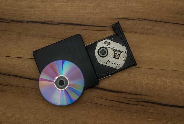
Optical storage is the oldest use of this technology in computers. Even as SSDs and cloud storage spread, optical media still matters. Especially long-life solutions like M-DISC archiving keep it alive. Moreover, game consoles and media players still use optical disc drives (ODDs).
In this section, we’ll examine CD, DVD, and Blu-ray drives layer by layer. I’ll show how wavelength affects storage capacity. Then we’ll dive into the internal architecture of the optical read head.
How Wavelength Determines Capacity in CD, DVD, and Blu-ray
The answer lies in the laws of physics. The diffraction limit of light sets the smallest spot you can focus. As wavelength shortens, the focus point shrinks. A smaller focus point means denser data on the disc. The whole optical storage revolution rests on this simple principle.
| Feature | CD Drive | DVD Drive | Blu-ray Drive |
|---|---|---|---|
| Laser Wavelength | 780 nm (infrared) | 650 nm (red) | 405 nm (blue-violet) |
| Focus Point Diameter | ~2.1 µm | ~1.3 µm | ~0.58 µm |
| Pit and Land Size | ~0.83 µm | ~0.4 µm | ~0.15 µm |
| Track Pitch | 1.6 µm | 0.74 µm | 0.32 µm |
| Single-Layer Capacity | 700 MB | 4.7 GB | 25 GB |
| Numerical Aperture (NA) | 0.45 | 0.60 | 0.85 |
| Laser Diode Used | GaAlAs | InGaAlP | GaN (Gallium Nitride) |
As you see in the table, it all starts with wavelength. In a CD reader, we use a 780 nm infrared beam. For DVD, we switch to a 650 nm red beam. Blu-ray uses a 405 nm blue-violet beam. As the wavelength shrinks, storage capacity multiplies.
Moreover, the numerical aperture (NA) is also a key factor. It shows how tightly the lens can focus the light. In Blu-ray disc systems, we use a very high NA of 0.85. This shrinks the focus point even more. As a result, we fit 25 GB of data on a single layer.
Why didn’t we jump straight to the shortest wavelength? The answer lies in semiconductor material science. Making a blue diode required developing gallium nitride (GaN) technology. This became possible in the late 1990s. Thus, Blu-ray disc technology is a result of the semiconductor laser revolution.
Inside the Optical Read Head: The Data-Reading Symphony of the Diode, Lens, and Photodetector
The heart of an optical drive is a complex module called the optical pickup head. Inside it, three key parts work together. They are the laser diode, the focusing lens, and the photodiode (photodetector) array. Each one operates in perfect harmony.
The process works like this. The diode produces continuous or pulsed light. This light passes through a series of lenses and focuses onto the disc surface. The aluminum reflective layer reflects the light back. The returning light goes through a beam splitter. Then it reaches the photodiode array.
We encode data on the disc as pits and lands. When light hits a pit, destructive interference occurs. Thus, less light returns to the photodiode. When it hits a land, the light reflects strongly. We interpret these brightness differences as 0 and 1.
I must also explain two vital servo systems here. The tracking servo keeps the light beam on the disc tracks. The focus servo keeps the light sharply focused. Both are continuously running closed-loop control systems. Without them, reading data is impossible.
The read head also contains some sensitive detectors. For example, a PIN photodiode or an avalanche photodiode (APD). These convert the weak returning light into an electrical signal.
Then the digital signal processing (DSP) circuit cleans this analog signal. Next, it turns it into a 0-1 sequence. We repeat this process millions of times per second.
Diode Aging and Optical Drive Failures: Diagnosis and Solution
Semiconductor laser diodes wear out over time. We call this diode aging. As aging progresses, the threshold current rises. As a result, the component draws more current to produce the same light output. This leads to read errors.
How do you detect an optical drive failure? Here is a checklist based on years of experience.
- The disc won’t read or appears late. Constant write errors may mean the diode is weak. The dark current level may also have risen.
- The drive makes a clicking sound. This usually comes from the focus or tracking servo recalibrating nonstop. The pickup can’t find the track, so the lens moves back and forth.
- It only reads certain discs. Recordable discs (DVD-RW) reflect less light than factory ones. A weak diode then fails to read them.
- Data transfer speed fluctuates. The read speed drops because error correction continues to engage. This means the optical signal-to-noise ratio (OSNR) has worsened.
Now let’s look at solutions. The first step is always cleaning the optical drive lens. You can use special cleaning discs for this. Also, opening the drive and gently cleaning with isopropyl alcohol works. However, this job requires experience.
If lens cleaning doesn’t help, the problem is diode aging. Unfortunately, the optical read head has reached its end of life. You need to buy a new drive, because replacing the diode is not cost-effective and recalibration requires special equipment.
Precise Positioning and Sensing: Laser Interferometry in Hard Drives
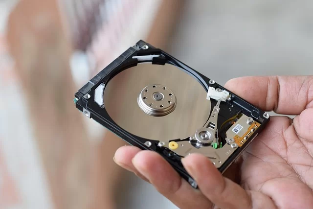
Hard disk drives (HDDs) are still the backbone of data centers. In 2026, 30 TB HDDs are on the market. This huge capacity needs incredible precision. The read-write head flies just a few nanometers above the disk. We use this light to control that distance.
Now I’ll detail interferometry in HDDs. Also, I’ll explain how we control flying height. This is one of the most impressive feats in computer engineering.
Positioning the Hard Drive Head with Nanometer Precision
Inside an HDD, the read head glides over a disk spinning at 7200 RPM. It must stay on the correct track. Plus, it must position itself to within a millionth of a millimeter. This is where the beam comes in.
Laser interferometry measures distance using the interference properties of light. Here’s how it works. We split a light beam into two. One beam goes to a reference mirror, the other to the measurement point. When the two return beams recombine, an interference pattern forms.
Each fringe in this pattern represents a distance of half a wavelength. For example, with a 633 nm helium-neon laser, you can detect movements of 316.5 nm. Today’s HDDs reach a precision of 0.1 nm. This is truly a mind-boggling value.
We use interferometry for two purposes in HDD manufacturing. First, for servo writing. While writing guide tracks on the disk, the interferometer gives absolute position reference. Second, for quality control testing. Every disk undergoes interferometric testing before leaving the factory.
Flying Height Control with Interferometry
The read head’s flying height is critical. This is the gap above the disk. In modern HDDs, it’s under 5 nm. A DNA helix is 2.5 nm wide, for comparison.
If the flying height is too high, the signal weakens and read errors increase. If it’s too low, the head crashes into the disk, causing data loss. Therefore, we calibrate each head’s flying height during production. We do this with great precision. Again, we use the beam.
The system sends a light beam into the gap between head and disk. We analyze the phase shift of the reflected light. This lets us calculate the gap distance in real time. Then a heating element on the head activates. It adjusts flying height by controlling thermal expansion.
We call this technology Thermal Flying Height Control (TFC). Your HDD performs this adjustment thousands of times per second. You do not even notice any of it occurring. I think this is one of the most fascinating achievements in modern computer engineering.
Laser in Input Hardware: Mice and Scanners
Now let’s move from storage units to peripherals. Input devices are the closest touchpoint between user and computer. In most of these, the light silently does its job. Mice and barcode scanners use this technology heavily.
In this section, I’ll compare laser and optical mice in depth. I’ll also put sensor technology in gaming gear under the microscope.
Laser Mouse vs. Optical Mouse: CMOS Sensor and Surface Detection Differences
Mouse technology has evolved significantly over the last 20 years. We went from mechanical ball mice to optical ones, then to laser devices. Today we talk about special technology like BlueTrack and Darkfield. What, then, are the differences between these technologies?
An optical mouse uses a red LED as its light source. This LED light hits the surface and reflects. The CMOS sensor captures images of this reflection thousands of times per second. The optical flow sensor compares consecutive frames and calculates movement. In short, the system is quite simple but effective.
A laser mouse uses a diode for lighting. When the light hits the surface, a speckle pattern forms. This pattern comes from the surface’s microscopic roughness. The CMOS sensor captures this pattern in far more detail than an optical mouse. This allows much more precise tracking.
| Feature | Optical Mouse | Laser Mouse |
|---|---|---|
| Light Source | Red LED | Laser Diode (usually 850 nm VCSEL) |
| Surface Compatibility | Good on matte surfaces | Most surfaces, including glossy and glass |
| DPI Resolution Range | 800 – 8,000 DPI | 200 – 30,000+ DPI |
| Acceleration Tracking | 20-35 G | 50 G and above |
| Lift-off Distance | Generally high (~2-3 mm) | Adjustable, very low (~1 mm) |
| Power Consumption | Lower | Slightly higher |
| Price | Budget | Mid-to-high end |
You often ask why a laser mouse works on glass. The answer lies in speckle pattern analysis. A glass surface looks smooth but is rough enough at the micro level. The diode’s sensitivity is high enough to detect this micro-roughness. LED light can’t capture such details.
DPI (dots per inch) resolution and CPI (counts per inch) sensitivity also matter. High DPI means the mouse detects small movements better. The sensors can reach up to 30,000 DPI. This offers a significant advantage, especially on high-resolution monitors.
Sensor Technology in Gaming Gear and Barcode Scanner Principles
Gaming mouse sensor technology is far more advanced than standard office mice. In these mice, hardware tracking precision and acceleration tracking are critical. Furthermore, we specially optimize the surface scanning algorithm. Professional gamers demand tracking speeds over 400 IPS.
We design the sensor PCB circuits specially for gaming mice. We process the raw sensor data on a built-in microcontroller. This processor calculates motion vectors and sends them to the motherboard via USB. The entire process happens in under 1 millisecond. Lag is unacceptable for gamers.
Besides, the working principle of barcode scanners is another use of this light. A barcode reader scans a beam across the barcode using a rotating mirror system (polygon mirror). Black bars absorb light, white spaces reflect it. A photodiode detects these reflections and decodes the barcode’s data.
How does a barcode scanner send data to a computer? It usually uses the USB HID protocol. The scanner presents itself as a keyboard and sends the barcode data as a string. Thus, you can type directly into any text box. The system is extremely simple but brilliant.
Laser in Output Hardware: How a Printer Works in Six Steps
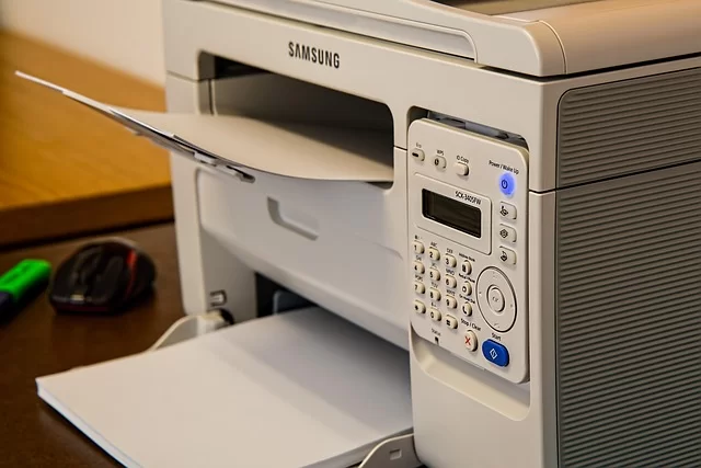
Now it’s time for output devices. Laser printers are essential in offices and homes. These machines can print dozens of pages per minute. They actually have a complex beam system. We call it the electrophotographic printing unit, a perfect blend of physics and electronics.
In this section, I’ll explain the six-step process of a printer step by step. Then I’ll compare laser and inkjet printers.
From Scanning Unit to Paper: The Six-Step Hardware Process
The working principle of a printer consists of six basic steps. We also know this process as xerography. Different parts come into play at each step. Let’s examine these steps in order.
- Cleaning: We clean the photoconductive drum of leftover toner from the previous print. A cleaning blade scrapes the drum surface. The waste toner goes to a reservoir.
- Charging: A corona wire or charge roller coats the drum with a uniform negative charge. This step brings the entire drum surface to the same potential. This high-voltage process occurs quietly.
- Writing/Exposure: The scanning unit comes into play. The diode turns on and off according to the image data. A rotating polygon mirror scans the beam line by line across the drum. The charge disappears from the points hit by light. This creates a latent image.
- Developing: A magnetic roller inside the toner cartridge brings negatively charged toner particles near the drum. Toner sticks only to the discharged areas. This is the final step before fusing.
- Transfer: As the paper passes under the drum, we apply a positive charge from behind. This transfers the toner from the drum to the paper. This transfer process happens with very high efficiency.
- Fusing: The fuser unit has two rollers heated to 392°F (200°C). The paper with toner passes between these rollers. Heat and pressure permanently bond the toner to the paper. This completes the print.
It completes these six steps in seconds. In color models, we repeat this process for four different toners. It’s truly a fascinating engineering marvel.
Laser Printer vs. Inkjet: Hardware Architecture Comparison
| Feature | Laser Printer | Inkjet Printer |
|---|---|---|
| Print Technology | Electrophotographic (dry toner + laser) | Thermal or piezoelectric jetting |
| Main Component | Drum, laser diode, fuser unit | Print head, ink cartridge |
| Print Speed | 20-100+ ppm | 5-20 ppm |
| Cost per Page | Low (toner lasts long) | High (ink is expensive) |
| Initial Cost | Medium-high | Low-medium |
| Monthly Duty Cycle | 2,000-20,000+ pages | 500-2,000 pages |
| Color Print Quality | Good (office quality) | Very good (photo quality) |
| Maintenance Need | Low (drum lasts long) | Medium (head may clog) |
| Heat Sink Cooling | Yes (fuser cooling) | Minimal |
My personal choice for high-volume offices is a laser printer. Its thermal management module keeps performance steady even during long runs. However, if you print photos, an inkjet printer gives better results. The choice depends entirely on your use case.
Laser Beam in Network and Communication Hardware: The Heart of Fiber Optic Internet
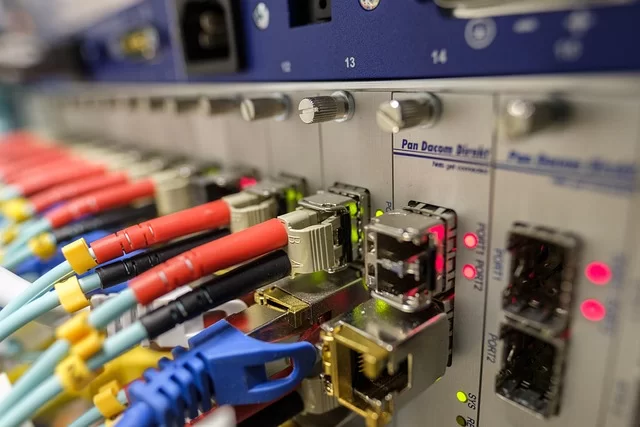
The beam in fiber optic cable is the backbone of the modern internet. Your home’s gigabit link is just light traveling inside glass fiber. Now I’ll examine the internal structure of SFP modules and WDM multiplexing technology.
Hardware Inside an SFP Module: How DFB Laser and Avalanche Photodiode (APD) Work
The SFP module is the standard interface for network cards. This small module contains incredible optoelectronic engineering. Each SFP module houses two basic optoelectronic parts. These are the transmitter and receiver sections.
On the transmit side, we use a DFB or VCSEL laser. A DFB unit produces a pure single wavelength thanks to its internal Bragg grating. This property is ideal for long-distance communication. We prefer VCSELs for lower-cost, short-range links.
On the receiver side, we have an avalanche photodiode (APD) or a PIN photodiode. The APD amplifies weak incoming light signals using its avalanche effect. Thus, it can detect signals that have suffered optical attenuation. Data transfer rates have reached 400 Gbps.
Fiber optic internet is fast because this optical signal is completely immune to electromagnetic interference (EMI). We don’t suffer signal degradation like in copper cables. Moreover, direct and external modulation techniques enable billions of bits per second.
Multiplying Bandwidth with WDM (Wavelength Division Multiplexing)
Can you send multiple data streams over a single fiber optic cable? Yes, wavelength division multiplexing (WDM) does exactly that. This technology combines beams of different colors in the same fiber. Each wavelength acts as an independent data channel.
Dense wavelength division multiplexing (DWDM) takes it even further. It can carry 80 or even 160 separate wavelengths on one fiber. Each channel runs at 400 Gbps. In total, a single fiber can theoretically transfer 64 Tbps. These numbers are truly breathtaking.
We often use Fabry-Perot laser diodes in these systems. Their low cost and wide temperature range offer advantages. However, for DWDM, the spectral purity of DFB units is preferred. The choice depends on budget and distance requirements.
The Future of Laser Beam in PCs: Silicon Photonics and Li-Fi Technologies
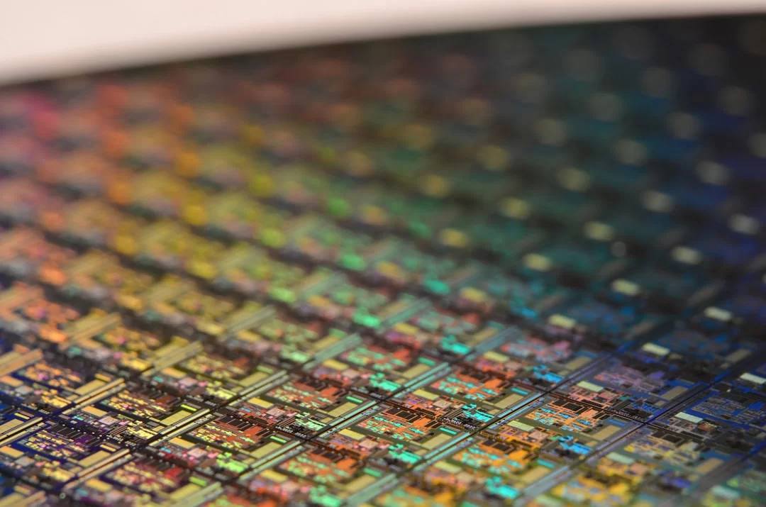
Welcome to the section on the future. Silicon photonics has the potential to radically change computer architecture. Li-Fi data transfer technology could also redefine wireless communication. Let’s examine these two technologies closely.
Silicon Photonics: Will Light Replace Copper on Motherboard Data Buses?
You often ask what silicon photonics is. Let me explain it simply. This technology aims to produce and direct light on silicon chips. It uses optical interconnects instead of traditional copper data buses. Data transfer then happens at nearly the speed of light.
Intel and IBM have been researching silicon photonic interconnects for years. As of 2026, the first optical data bus prototypes are working. These systems promise terabit-per-second speeds over motherboard buses. Additionally, energy efficiency is much higher than that of copper cables.
Thanks to optical interconnects, we can build microprocessor optical links directly at the chip level. This is revolutionary for hardware integration. The data bottleneck between CPU and GPU could vanish. As silicon chip integration costs fall, this technology will spread.
This change will be significant for computer architecture. Manufacturers will completely redesign motherboards. Optical data buses will replace copper traces. Moreover, lithography will enable more complex chip structures. The future is truly exciting.
Li-Fi: Data Transfer via Your Computer’s LED or Light Source
Li-Fi (Light Fidelity) is a wireless technology based on visible light communication (VLC). LEDs or diodes turn on and off millions of times per second to transmit data. This switching is too fast for the human eye to see. Thus, you get both light and data.
Li-Fi has significant advantages over Wi-Fi. There’s no electromagnetic interference (EMI) issue at all. Light can’t pass through walls, so the connection is naturally secure. Moreover, theoretical speeds have reached 224 Gbps. That’s far beyond Wi-Fi 7.
Infrared LED sensors and VCSEL technology are two different approaches for Li-Fi. LEDs are cheaper but have limited bandwidth. VCSEL-based systems are faster. Additionally, beam modulation can reach much higher frequencies. The higher the modulation frequency, the faster the data rate.
The thermal management module is critical in Li-Fi systems. Diodes heat up when running at high frequency. Heat sink cooling keeps this heat at a safe level. Otherwise, performance drops and aging accelerates.
Hardware-Focused Safety: Standards and Classifications
Safety is one of the most serious topics in computing. The light in PC components is generally low-power. Still, it carries certain risks. In this section, I’ll cover safety standards and classifications.
IEC 60825-1 Standard and the Hardware Equivalents of Classes
The IEC 60825-1 standard defines the safety classification of laser beam products. This international standard is binding for all manufacturers. There are five main classes: 1, 2, 3R, 3B, and 4. Each class represents different power levels and safety measures.
- Class 1: Completely safe under normal use. Optical drives and mice fall into this class. Maximum power is limited to 0.39 mW.
- Class 2: Emits up to 1 mW of visible light. The blink reflex provides protection. You see these in barcode scanners.
- Class 3R: Can go up to 5 mW. Short-term exposure is generally harmless. Still, avoid looking directly at the beam.
- Class 3B: Carries up to 500 mW of power. There is a serious eye injury risk. You must use safety goggles.
- Class 4: Exceeds 500 mW. It poses fire and retina damage risks. Found in industrial etching devices.
What Does the ‘Class 1 Product’ Label on Your Hardware Mean?
You see a Class 1 label on most computer parts. This label gives you important assurance. The device is completely safe under normal operating conditions. The focused beam never escapes the housing.
However, remember this. If you open the device and look inside, that protection vanishes. The diode in an optical drive emits at 780 nm. This infrared light is invisible. Your pupil does not constrict reflexively against it. Thus, the retina damage risk increases significantly.
The optical power density inside drives like CD-ROM and DVD-RW is low. Still, you should never look directly at it. Moreover, never disassemble any optical drive without goggles. Safety comes first.
The Critical Role of Light in Computer Hardware
This light is an essential part of computer hardware. It offers a wide range of uses from optical drives to printers. Additionally, it plays a vital role in fiber optic communication.
- Wikipedia – Laser Light: Explains the definition, working principle, and history comprehensively. Also touches on its applications in computer hardware.
- Science – Integrated Light Chip: Technically examines how integrating light into computer chips can increase processing speeds.
- HowStuffWorks – Light Principles: Shows the basic working logic step by step, from production to its role in data reading/writing.
- Wikipedia – Optical Disc Drives: Explains in detail how optical drives read and write data using light.
FAQ About Laser Beam Technology in Computer Hardware
What happens if the beam in my optical drive fails?
What are the hardware differences between a laser mouse and an optical mouse?
How exactly does data reading and writing work with a beam?
Why do CD, DVD, and Blu-ray readers have different wavelengths?
Does the light affect the speed of my fiber optic internet connection?
How does the drum unit of a printer interact with the beam?
How should I clean my computer’s optical drive lens?
When will silicon photonics technology start being used in next-generation computers?
What are the 3 basic hardware differences between laser light and normal light?
Why doesn’t my Windows Hello facial recognition hardware use a laser?
Conclusion: The Silent Revolution of Light in PC Hardware
We’ve examined eight key uses of this technology in computers. As you can see, it’s far more common than we think. It appears everywhere. For example, optical storage, networking, printers, and future silicon photonic chips.
The Past, Present, and Photonic Future of Light in Hardware Engineering
The journey that started with CD-ROM in the 1980s now extends to photonic integrated circuits. This light no longer just reads data. It also enables on-chip communication, precise positioning, and wireless data transfer. This evolution continues unabated.
I’m especially excited by advances in hardware integration. Silicon photonic chips will soon appear in all our computers. Li-Fi will radically change wireless communication. The next decade will be incredible for computer engineering.
I believe in the potential of optical interconnect technology. We’ve reached the physical limits of copper data buses. Light offers almost limitless bandwidth. This transformation will completely reshape computer architecture.
Recommendations for Users: Pay Attention to This Technology When Choosing Hardware
Finally, I want to offer a few practical tips. Paying attention to this technology when buying PC parts will benefit you in the long run.
- Prioritize Blu-ray support when choosing an optical drive. It offers the highest data density thanks to 25 GB capacity and a 405 nm blue diode. Also, M-DISC archiving compatibility is ideal for long-term backups.
- Choose sensor-based models when buying a mouse. This is crucial if you’ll use it on tricky surfaces like glass. Therefore, check the DPI resolution and maximum acceleration tracking.
- Use network cards with SFP modules if you have fiber optic infrastructure. Distributed feedback laser (DFB)-based modules run more stably over long distances. However, for short distances, VCSEL is sufficient and more affordable.
- Check the monthly duty cycle when buying a laser printer. If you heavily use a low-capacity model, the fuser unit wears out early. The quality of the thermal management module also directly affects print lifespan.
- Don’t neglect lens cleaning for older optical drives. A simple cleaning every six months significantly extends the optical pickup’s life. This also delays the effects of diode aging.

Be the first to share your comment