
In this article, I will look at the steps for creating a Virtual Local Area Network (VLAN) with the GNS3 simulator. I will also talk about routing between VLANs on a Cisco Layer 2 Switch.
First, I will show the simple steps needed to make separate broadcast areas with GNS3. In the end, this setup will let different VLANs talk well and make the network faster and safer.
I will clearly explain each step of the setup by looking at specific commands and settings. In short, if you are new or you know networks well, you will understand the process better by using our guide.
Creating and Configuring VLANs in GNS3: A Step-by-Step Guide
With GNS3, you and other network planners can build exact network designs. Also, you can change these plans for different situations.
In short, you can build strong network topologies using Dynamips. For this, you use the IOS images from Cisco Routers and Switches. This lets you closely copy real network setups.
Our current design uses GNS3. We add virtual machines running on VMware Workstation. These act like client computers. But we will look at another way: VPCS (Virtual PC Simulator).
VPCS is a simple tool for VLAN setup with GNS3. It allows for fast network testing. Furthermore, it helps your host computer run better by not using heavy virtual machines.
You should know that VPCS is suitable for many uses. But there are also times when you need complete virtual machines.
This is very true when we must test special operating systems. Also, some programs need a complete computer setting for testing.
In past articles, I explained how to add a Layer 2 Switch to GNS3. Now, I’ll explain how to create and configure a VLAN (Virtual Local Area Network) on an L2 device.
First, we will set up VLANs. Then, we’ll assign switch ports. Finally, we will make sure devices can talk. This will help us learn about splitting networks and traffic control.
How to Add a VLAN in a Switch and Configure Inter-VLAN Routing in a Router
In this article, we will discuss the following steps;
- Assigning an IP Address to VPCS
- Creating a VLAN
- Determination of Switch Trunk Ports
- Trunking Between Switches
- Cisco Router Inter-VLAN Configuration
1. Create Topology for VLAN in GNS3
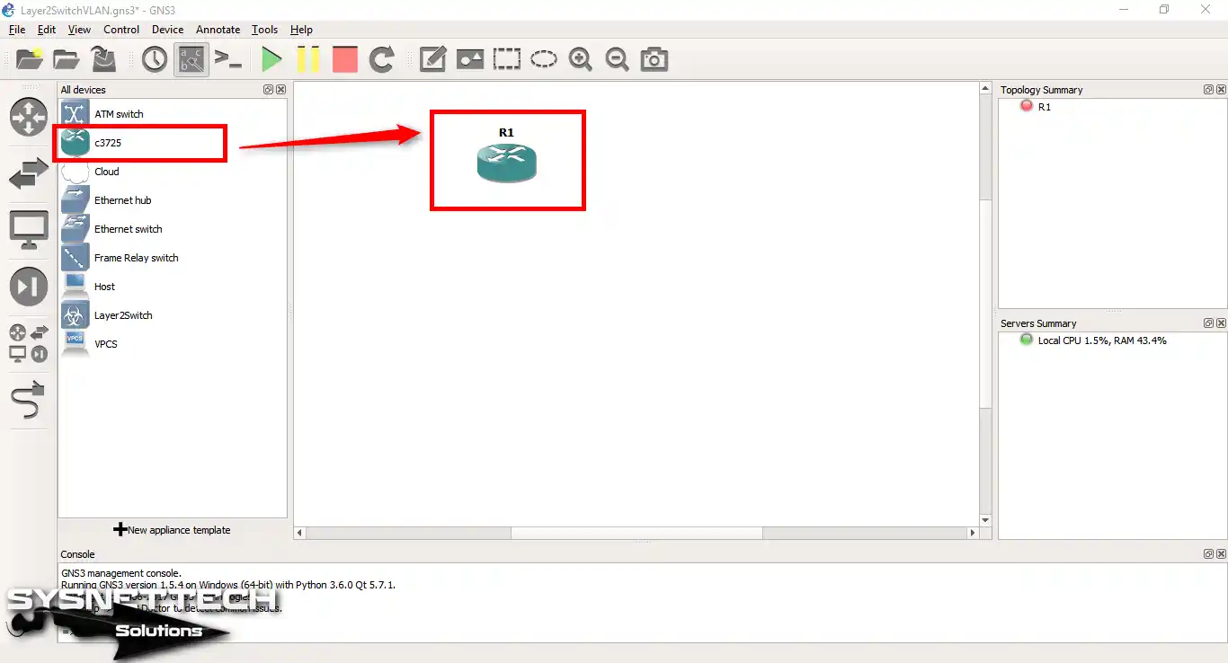
Step 1
To configure VLAN in GNS3, first, add a Cisco Router to the workspace.
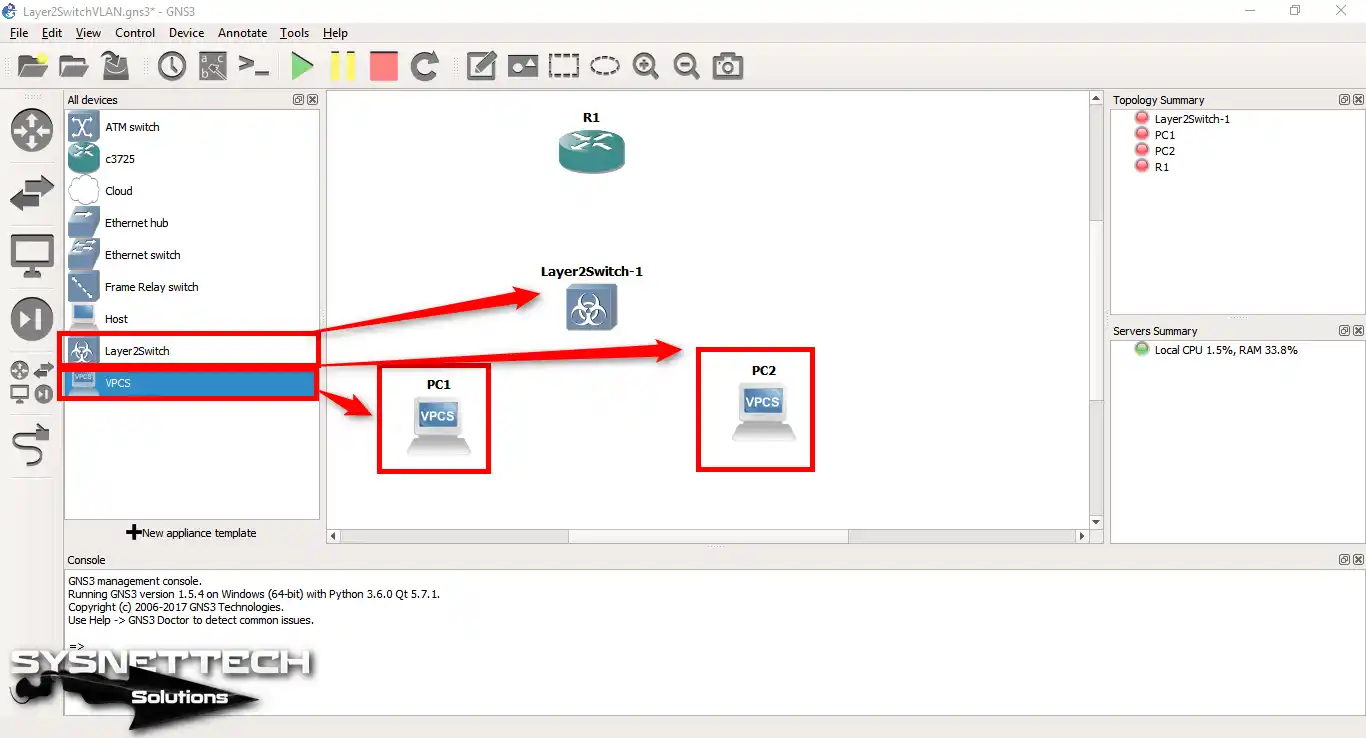
Step 2
Add a Layer 2 Switch & 2 VPCS computers to the workspace.
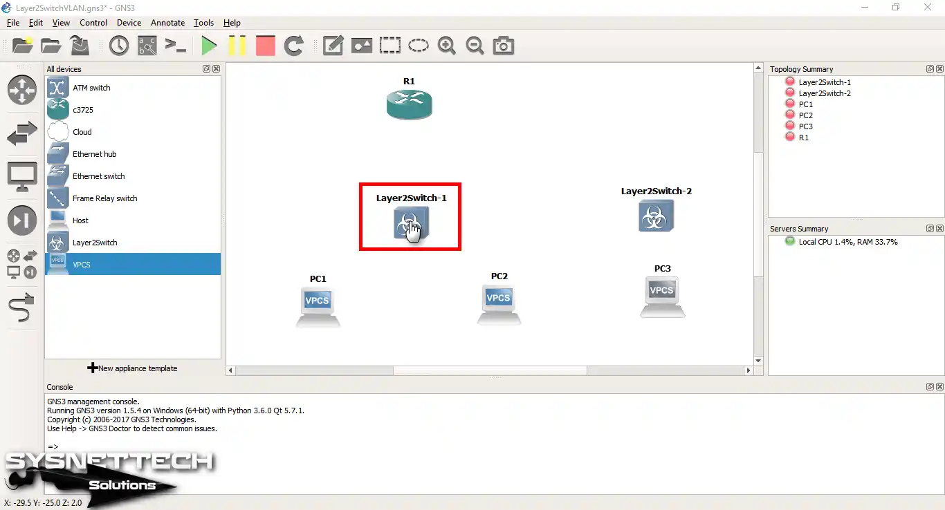
Step 3
Add another Layer 2 Switch and VPCS.
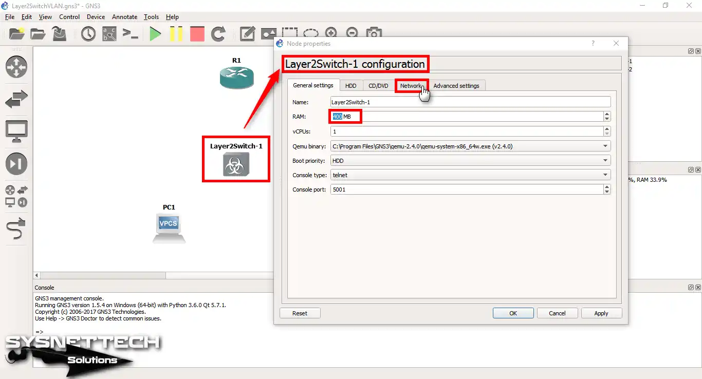
Step 4
Right-click / configure on the Layer 2 Switch. In the window that opens, increase the amount of RAM for the Switch. Since the L2 Switch is Qemu-based, boot problems with low RAM may occur.
Set the Cisco L2 Switch RAM to 400 MB and then click the Network tab.
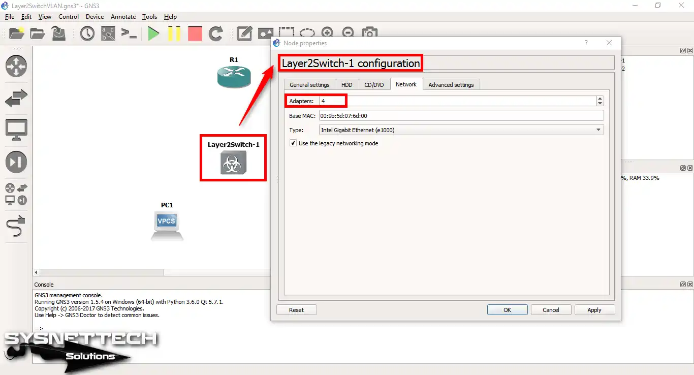
Step 5
On the Network tab, set the number of Adapters to 4 to add an interface to the Switch.
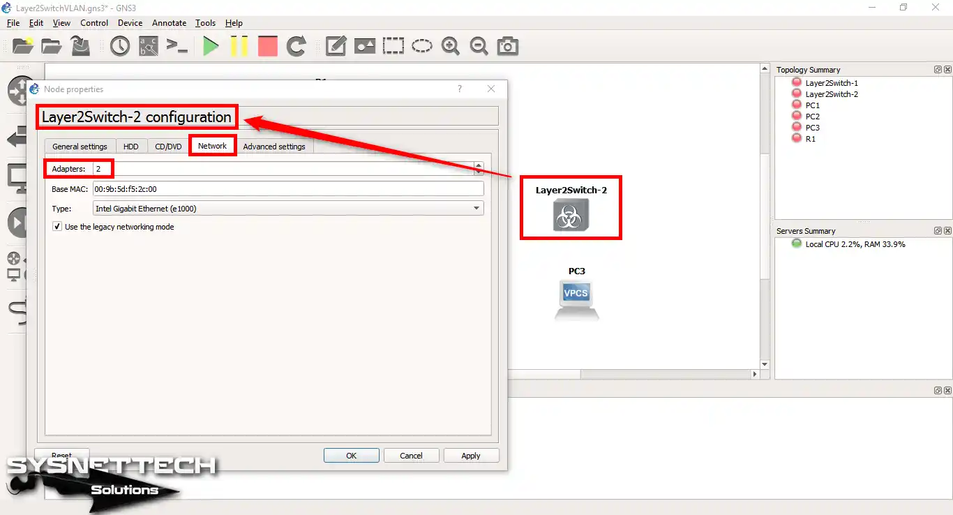
Step 6
Since we will use two interfaces on Switch-2, 300 MB RAM is enough.

Step 7
Add 2 interfaces from the Network tab.
Step 8
After you finish the last steps, pick the cable tool from the menu. Then, link all devices in the work area like our drawing shows. Keep going, making sure you have made every link.

2. Assign IP to VPCSs
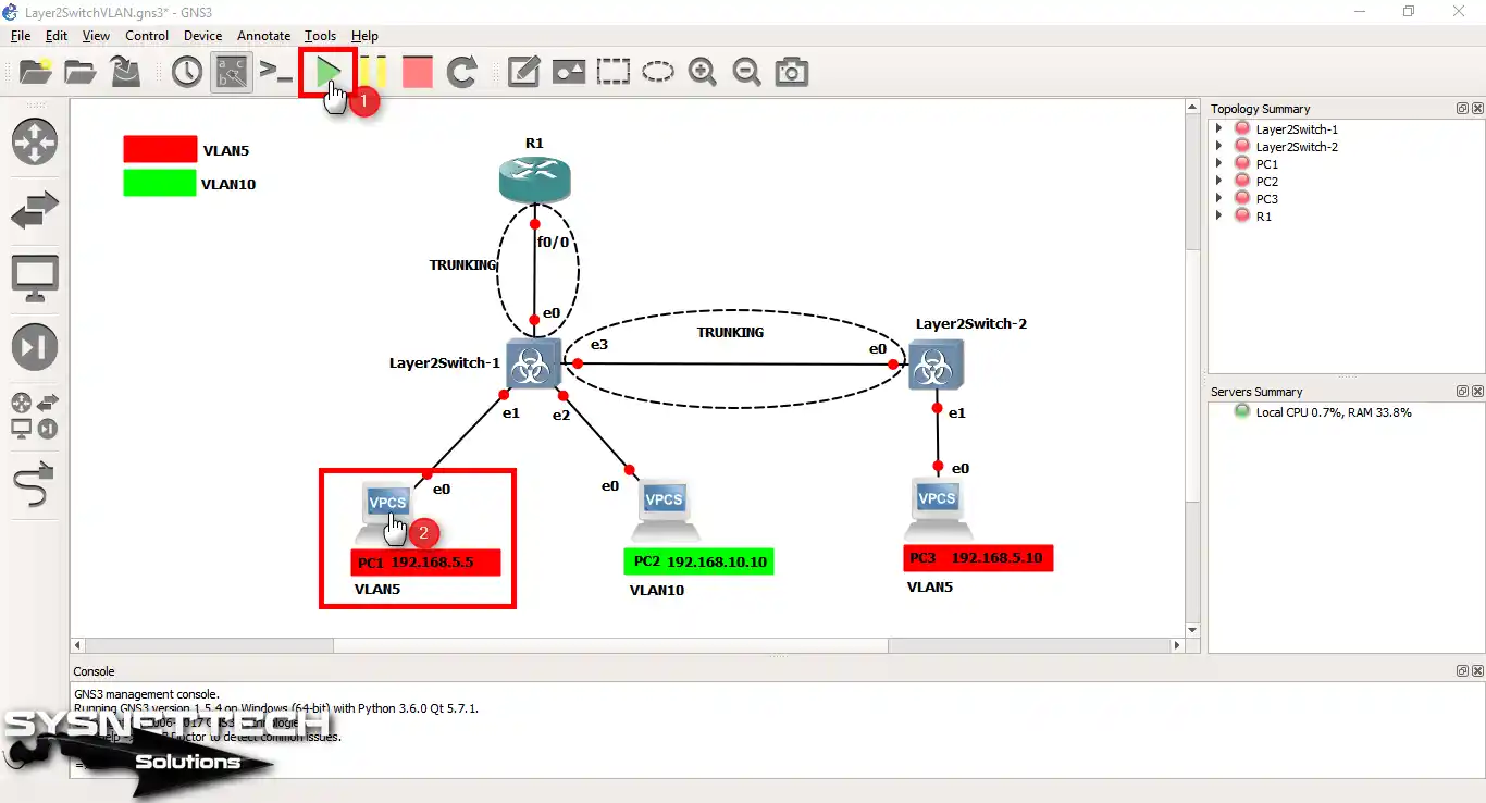
Step 1
The latest status of the network topology is shown in the following image. After you determine the VLANs on the network topology, you must configure the TCP/IP settings for the VPCSs.
Next, create a trunk connection between the Cisco Switches. Next, you need to configure the connection between R1 and SW1 as a trunk.
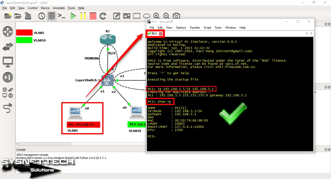
Now, double-click to assign an IP address to the VPCS PC1.
Step 2
Type the following command to assign an IP address to PC1 and press Enter. To view the IP configuration, use the show ip command.
ip 192.168.5.5/24 192.168.5.1
Step 3
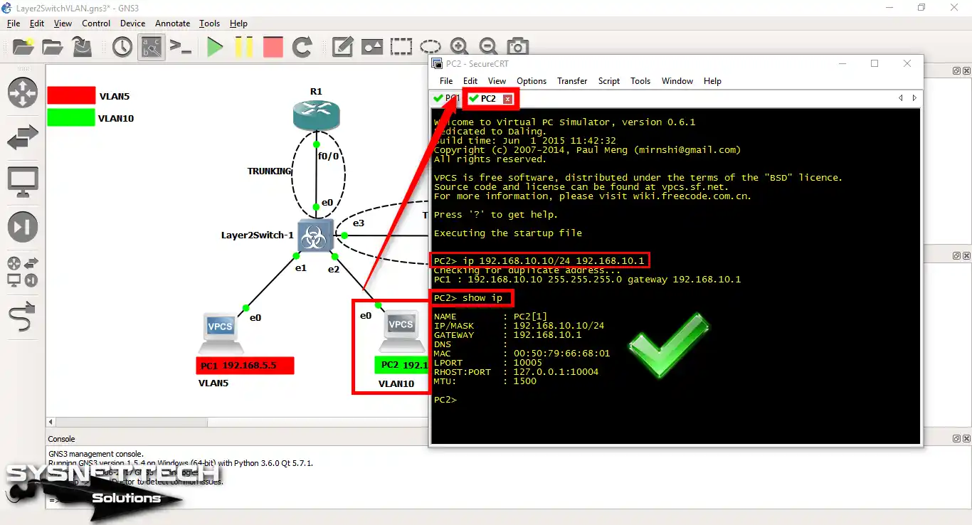
Run the next command to give the IP address to the VPCS PC2.
The critical point here is to take steps according to the notes on the network topology.
Since PC2 will be a member of VLAN 10, the IP address will be different.
ip 192.168.10.10/24 192.168.10.1
Step 4
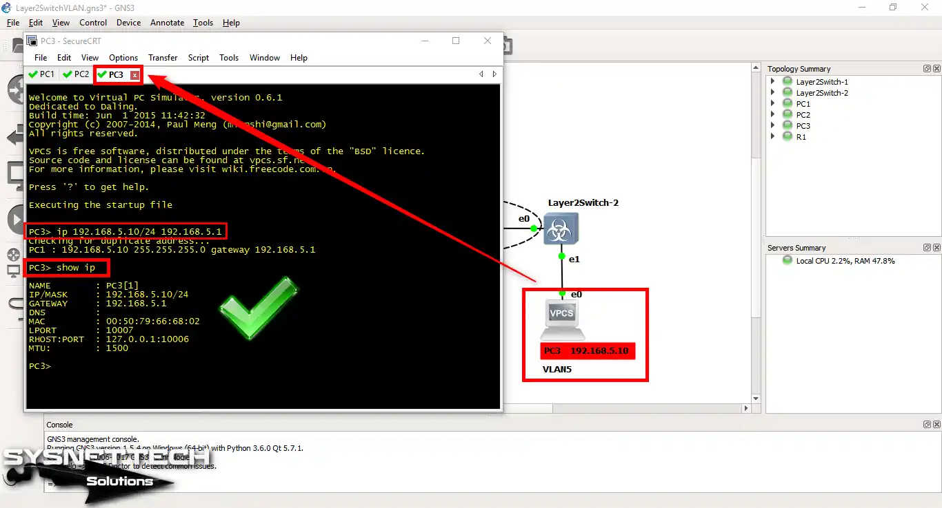
Configure the IP address settings for VPCS PC3, which will be members of VLAN5, as follows:
ip 192.168.5.10/24 192.168.5.1
3. Create VLANs on Layer 2 Switches
Step 1
Click on Layer 2 Switch-1 & Switch-2 to configure Cisco Switches.
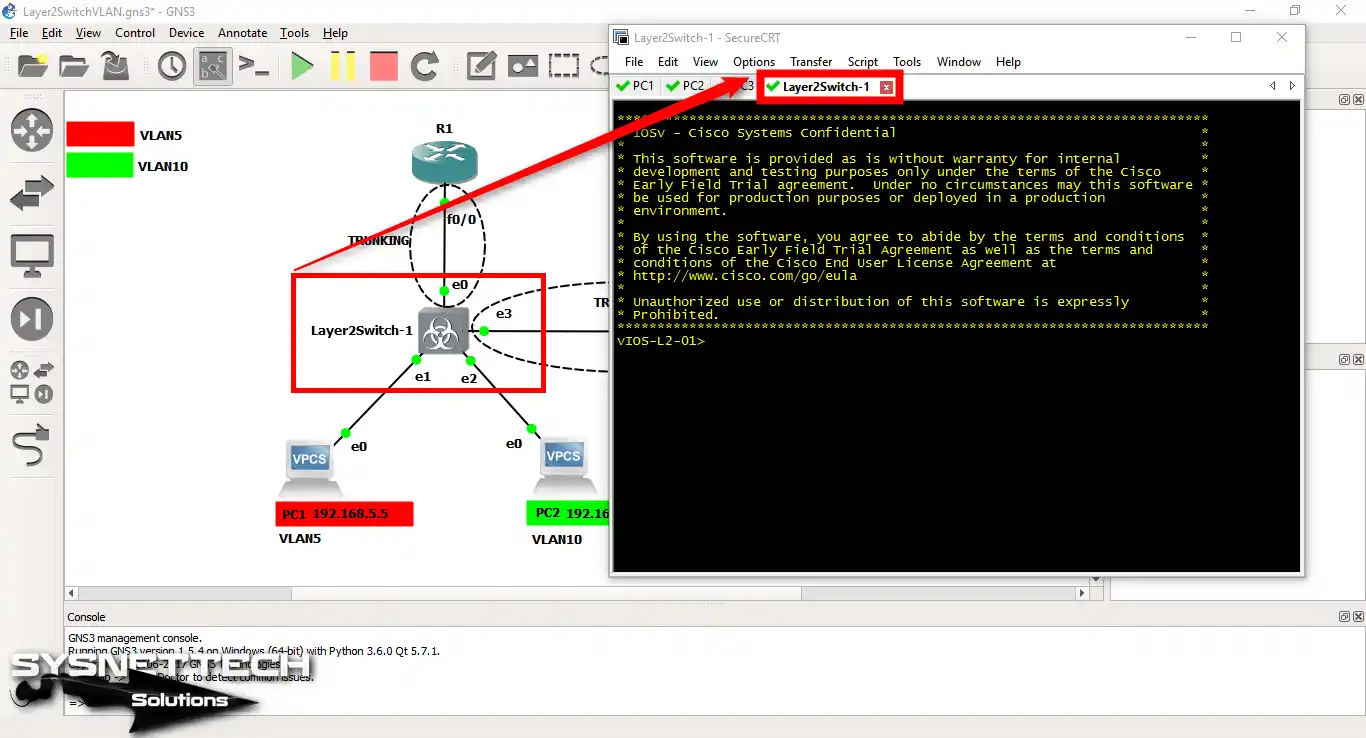
Step 2
Follow the instructions below to create a VLAN on the switches.
- L2 Switch-1
vIOS-L2-01# conf t
vIOS-L2-01(config)# vlan 5
vIOS-L2-01(config-vlan)# name IT
vIOS-L2-01(config-vlan)# exit
vIOS-L2-01(config)# vlan 10
vIOS-L2-01(config-vlan)# name SALES
vIOS-L2-01(config-vlan)# exit
vIOS-L2-01(config)# end
vIOS-L2-01# wr- L2 Switch-2
vIOS-L2-01# conf t
vIOS-L2-01(config)# vlan 5
vIOS-L2-01(config-vlan)# name IT
vIOS-L2-01(config-vlan)# exit
vIOS-L2-01(config)# end
vIOS-L2-01# wr
Step 3
You must set up the L2 Switch ports. First, set up the ports linked to the Cisco Router. Then, set these ports as Trunks on the L2 Switch.
Use these commands to set the Access and Trunk ports. Also, put the computers into their own VLANs.
vIOS-L2-01(config)#interface gigabitethernet 0/1
vIOS-L2-01(config-if)#switchport mode access
vIOS-L2-01(config-if)#switchport access vlan 5
vIOS-L2-01(config-if)#exit
vIOS-L2-01(config)#
vIOS-L2-01(config)#interface gigabitethernet 0/2
vIOS-L2-01(config-if)#switchport mode access
vIOS-L2-01(config-if)#switchport access vlan 10
vIOS-L2-01(config-if)#exit
vIOS-L2-01(config)#
vIOS-L2-01(config)#interface gigabitethernet 0/3
vIOS-L2-01(config-if)#switchport trunk encapsulation dot1q
vIOS-L2-01(config-if)#switchport mode trunk
vIOS-L2-01(config-if)#exit
vIOS-L2-01(config)#
vIOS-L2-01(config)#interface gigabitethernet 0/0
vIOS-L2-01(config-if)#switchport trunk encapsulation dot1q
vIOS-L2-01(config-if)#switchport mode trunk
vIOS-L2-01(config-if)#exit
vIOS-L2-01(config)#exit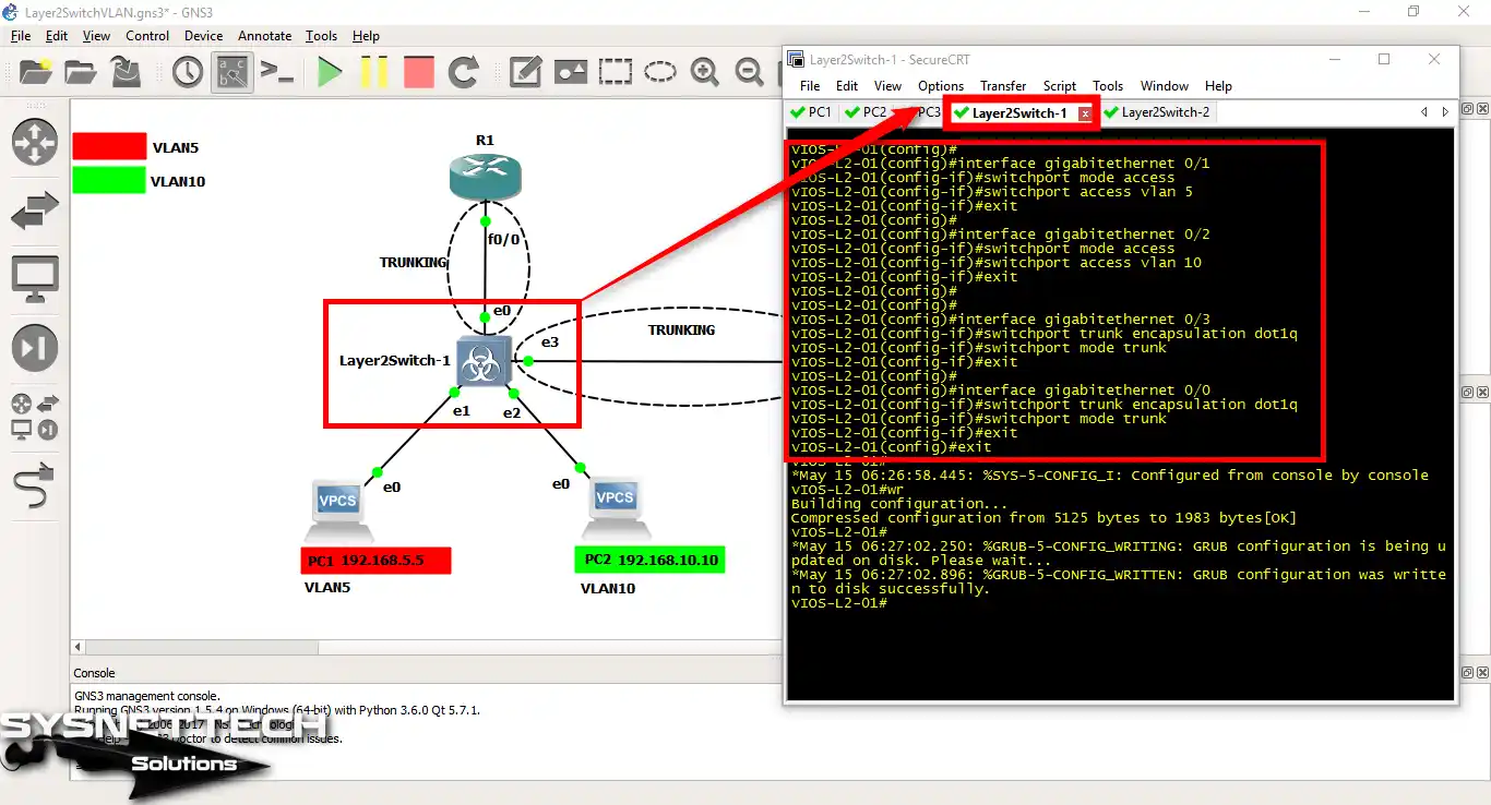
Step 4
Use the following commands to perform the same operations on Cisco Layer 2 Switch-2.
vIOS-L2-01# conf t
vIOS-L2-01(config)#interface gigabitethernet 0/1
vIOS-L2-01(config-if)#switchport mode access
vIOS-L2-01(config-if)#switchport access vlan 5
vIOS-L2-01(config-if)#exit
vIOS-L2-01(config)#
vIOS-L2-01(config)#interface gigabitethernet 0/0
vIOS-L2-01(config-if)#switchport trunk encapsulation dot1q
vIOS-L2-01(config-if)#switchport mode trunk
vIOS-L2-01(config-if)#end
vIOS-L2-01#wr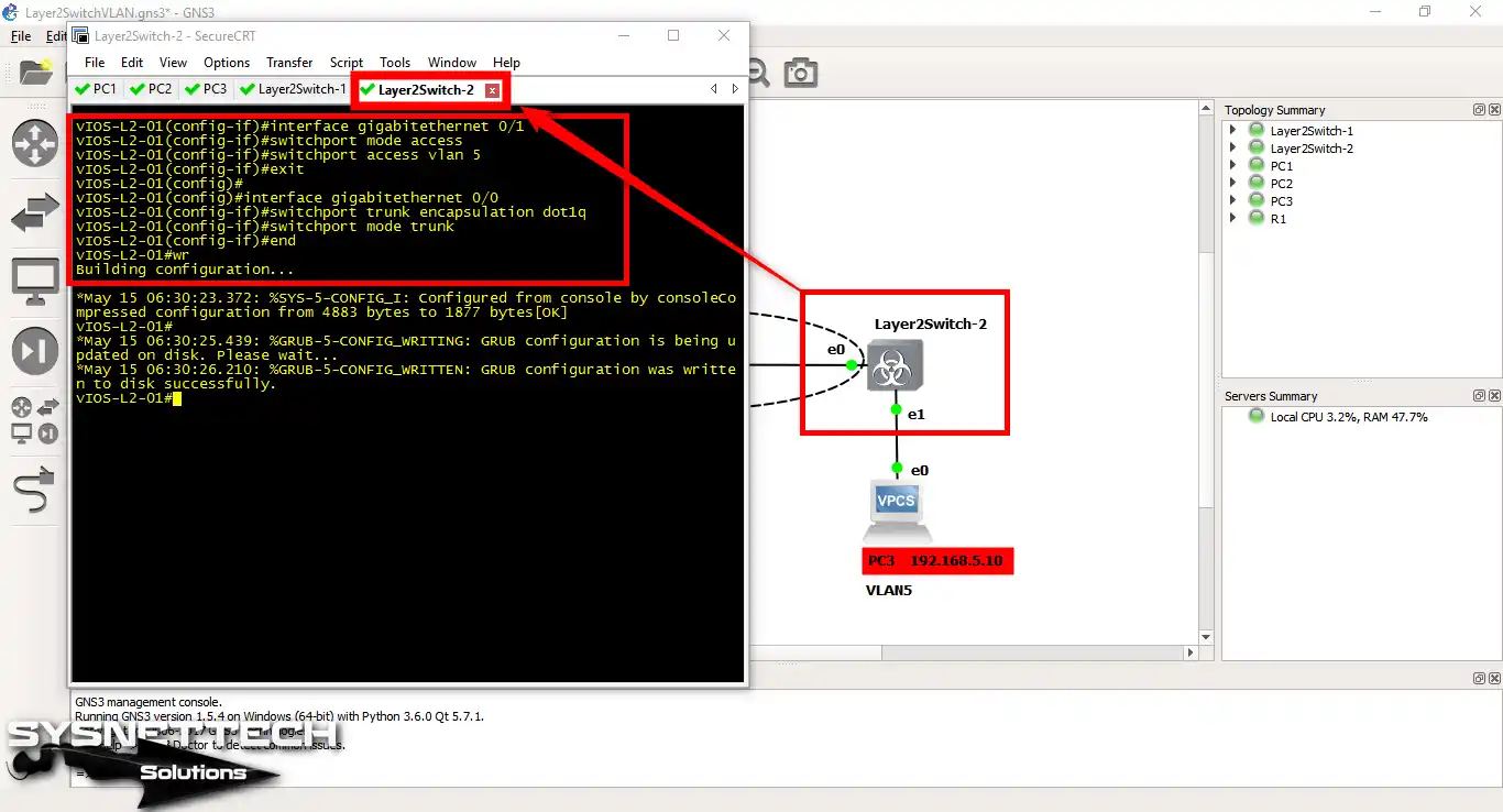
4. Configure Inter-VLAN Routing
Step 1
Up to this point, we have configured the VPCS computers and created VLANs. Next, we assigned the PCs to VLANs and implemented trunking.
In this step, open the command prompt, then click on R1 in the workspace. The reason for doing this is to implement VLAN routing.
Now, on the Cisco Router, run the following commands to route VLANs over one wire:
R1# conf t
R1(config)#interface fastethernet 0/0
R1(config-if)#no shutdown
R1(config-if)#exit
R1(config)#
R1(config)#interface fastethernet 0/0.5
R1(config-subif)#encapsulation dot1q 5
R1(config-subif)#ip address 19
*Mar 1 00:09:18.259: %LINK-3-UPDOWN: Interface FastEthernet0/0, changed state to up
R1(config-subif)#ip address 192.168.5.1 255.255.255.0
R1(config-subif)#no shutdown
R1(config-subif)#exit
R1(config)#
R1(config)#interface fastethernet 0/0.10
R1(config-subif)#encapsulation dot1q 10
R1(config-subif)#ip address 192.168.10.1 255.255.255.0
R1(config-subif)#no shutdown
R1(config-subif)#end
R1#wr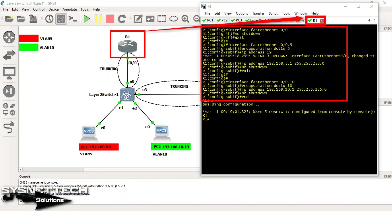
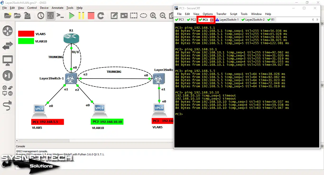
Step 2
Now, ping the PC2 to the V2 member PC2 and test the connection. Check that the routing between VLANs is working correctly.

Step 3
When you ping from PC2 to PCs that are members of VLAN5, you can see that the process is successful.

Step 4
Likewise, PC3 and VLAN10 will establish a healthy connection.
Show Commands in GNS3 VLAN Configuration
- PC1> ip
- PC2> ip
- PC3> ip
- show vlan brief
- show vlan brief
- show running-config
- show running-config
- show interfaces trunk
- show interfaces trunk
- R1#show running-config
PC1> ip 192.168.5.5/24 192.168.5.1
Checking for duplicate address...
PC1 : 192.168.5.5 255.255.255.0 gateway 192.168.5.1

PC1> show ip

NAME : PC1[1]
IP/MASK : 192.168.5.5/24
GATEWAY : 192.168.5.1
DNS :
MAC : 00:50:79:66:68:00
LPORT : 10003
RHOST:PORT : 127.0.0.1:10002
MTU: : 1500

PC1>
PC2> ip 192.168.10.10/24 192.168.10.1
Checking for duplicate address...
PC1 : 192.168.10.10 255.255.255.0 gateway 192.168.10.1

PC2> show ip

NAME : PC2[1]
IP/MASK : 192.168.10.10/24
GATEWAY : 192.168.10.1
DNS :
MAC : 00:50:79:66:68:01
LPORT : 10005
RHOST:PORT : 127.0.0.1:10004
MTU: : 1500

PC2>
PC3> ip 192.168.5.10/24 192.168.5.1
Checking for duplicate address...
PC1 : 192.168.5.10 255.255.255.0 gateway 192.168.5.1

PC3> show ip

NAME : PC3[1]
IP/MASK : 192.168.5.10/24
GATEWAY : 192.168.5.1
DNS :
MAC : 00:50:79:66:68:02
LPORT : 10007
RHOST:PORT : 127.0.0.1:10006
MTU: : 1500

PC3>
vIOS-L2-01#show vlan brief

VLAN Name Status Ports
---- -------------------------------- --------- -------------------------------
1 default active
5 IT active Gi0/1
10 SALES active Gi0/2
100 VLAN100 active
200 VLAN0200 active
300 VLAN0300 active
1002 fddi-default act/unsup
1003 trcrf-default act/unsup
1004 fddinet-default act/unsup
1005 trbrf-default act/unsup
vIOS-L2-01#show vlan brief

VLAN Name Status Ports
---- -------------------------------- --------- -------------------------------
1 default active
5 IT active Gi0/1
100 VLAN100 active
200 VLAN0200 active
300 VLAN0300 active
1002 fddi-default act/unsup
1003 trcrf-default act/unsup
1004 fddinet-default act/unsup
1005 trbrf-default act/unsup
vIOS-L2-01#
vIOS-L2-01#show running-config
Building configuration...

Current configuration : 5125 bytes
!
! Last configuration change at 06:26:58 UTC Mon May 15 2017
!
version 15.0
service timestamps debug datetime msec
service timestamps log datetime msec
no service password-encryption
service compress-config
!
hostname vIOS-L2-01
!
boot-start-marker
boot-end-marker
!
!
!
no aaa new-model
!
!
!
vtp domain CISCO-vIOS
vtp mode transparent
!
!
!
ip cef
no ipv6 cef
!
!
spanning-tree mode pvst
spanning-tree extend system-id
!
vlan internal allocation policy ascending
!
vlan 5
name IT
!
vlan 10
name SALES
!
vlan 100
name VLAN100
!
vlan 200,300
!
!
!
!
!
interface GigabitEthernet0/0
switchport trunk encapsulation dot1q
switchport mode trunk
media-type rj45
negotiation auto
!
interface GigabitEthernet0/1
switchport access vlan 5
media-type rj45
negotiation auto
!
interface GigabitEthernet0/2
switchport access vlan 10
media-type rj45
negotiation auto
!
interface GigabitEthernet0/3
switchport trunk encapsulation dot1q
switchport mode trunk
media-type rj45
negotiation auto
!
ip forward-protocol nd
!
no ip http server
no ip http secure-server
!
!
!
line con 0
logging synchronous
line aux 0
line vty 0 4
logging synchronous
login
line vty 5 15
logging synchronous
login
!
!
end

vIOS-L2-01#
vIOS-L2-01#show running-config
Building configuration...

Current configuration : 4883 bytes
!
! Last configuration change at 06:30:23 UTC Mon May 15 2017
!
version 15.0
service timestamps debug datetime msec
service timestamps log datetime msec
no service password-encryption
service compress-config
!
hostname vIOS-L2-01
!
boot-start-marker
boot-end-marker
!
!
!
no aaa new-model
!
!
!
vtp domain CISCO-vIOS
vtp mode transparent
!
!
!
ip cef
no ipv6 cef
!
!
spanning-tree mode pvst
spanning-tree extend system-id
!
vlan internal allocation policy ascending
!
vlan 5
name IT
!
vlan 100
name VLAN100
!
vlan 200,300
!
!
!
interface GigabitEthernet0/0
switchport trunk encapsulation dot1q
switchport mode trunk
media-type rj45
negotiation auto
!
interface GigabitEthernet0/1
switchport access vlan 5
media-type rj45
negotiation auto
!
ip forward-protocol nd
!
no ip http server
no ip http secure-server
!
!
!
line con 0
logging synchronous
line aux 0
line vty 0 4
logging synchronous
login
line vty 5 15
logging synchronous
login
!
!
end

vIOS-L2-01#
vIOS-L2-01#show interfaces trunk

Port Mode Encapsulation Status Native vlan
Gi0/0 on 802.1q trunking 1
Gi0/3 on 802.1q trunking 1

Port Vlans allowed on trunk
Gi0/0 1-4094
Gi0/3 1-4094

Port Vlans allowed and active in management domain
Gi0/0 1,5,10,100,200,300
Gi0/3 1,5,10,100,200,300

Port Vlans in spanning tree forwarding state and not pruned
Gi0/0 1,5,10,100,200,300
Gi0/3 1,5,10,100,200,300
vIOS-L2-01#
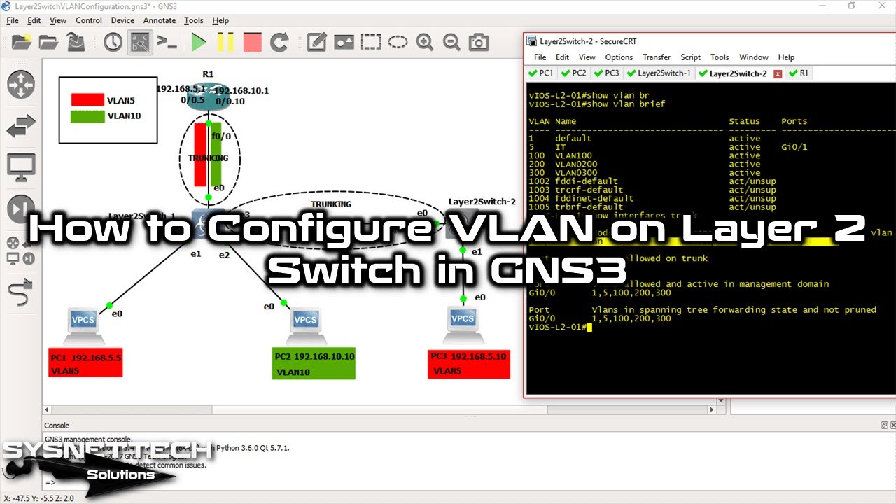
vIOS-L2-01#show interfaces trunk

Port Mode Encapsulation Status Native vlan
Gi0/0 on 802.1q trunking 1

Port Vlans allowed on trunk
Gi0/0 1-4094

Port Vlans allowed and active in management domain
Gi0/0 1,5,100,200,300

Port Vlans in spanning tree forwarding state and not pruned
Gi0/0 1,5,100,200,300
vIOS-L2-01#
R1#show running-config
Building configuration...

Current configuration : 1149 bytes
!
version 12.4
service timestamps debug datetime msec
service timestamps log datetime msec
no service password-encryption
!
hostname R1
!
boot-start-marker
boot-end-marker
!
!
no aaa new-model
memory-size iomem 5
no ip icmp rate-limit unreachable
ip cef
!
!
!
!
no ip domain lookup
ip auth-proxy max-nodata-conns 3
ip admission max-nodata-conns 3
!
!
!
!
ip tcp synwait-time 5
!
!
!
!
!
interface FastEthernet0/0
no ip address
duplex auto
speed auto
!
interface FastEthernet0/0.5
encapsulation dot1Q 5
ip address 192.168.5.1 255.255.255.0
!
interface FastEthernet0/0.10
encapsulation dot1Q 10
ip address 192.168.10.1 255.255.255.0
!
interface Serial0/0
no ip address
shutdown
clock rate 2000000
!
interface FastEthernet0/1
no ip address
shutdown
duplex auto
speed auto
!
ip forward-protocol nd
!
!
no ip http server
no ip http secure-server
!
no cdp log mismatch duplex
!
!
!
control-plane
!
!
!
gatekeeper
shutdown
!
!
line con 0
exec-timeout 0 0
privilege level 15
logging synchronous
line aux 0
exec-timeout 0 0
privilege level 15
logging synchronous
line vty 0 4
login
!
!
end

R1#
How to Enable VLAN ⇒ Video
I suggest you watch the video below to see how to turn on VLAN. I have given step-by-step directions and facts in our teaching video.
Please remember to join our YouTube channel, as this will help you finish the job well. This way, you will know about our new videos, and more helpful lessons will be there for you!
Frequently Asked Questions (FAQ) About GNS3 & VLAN
- What basic components do I need to configure VLANs with GNS3?
- How can I create a VLAN in the emulator?
- How can I assign switch ports to a VLAN?
- How can I verify that the VLAN setting is correct?
Conclusion
In the end, setting up VLANs in GNS3 lets us build good network topologies. In our guide, we first examined how to set up broadcast domains. Then, we assigned IP addresses to virtual machines.
Next, we set up inter-VLAN routing on the Router. Furthermore, using tools like VPCS allows for quick testing.
At the same time, the flexibility of Cisco L2 switches fits many needs. Learning these skills lets us plan better networks.
Also, our knowledge of traffic control and splitting grows. In short, when testing with GNS3, we must build VLAN rules on a strong base.
When setting up VLANs, controlling network traffic is also a key point. Because of this, we must also handle the STP. We can make the network work better by picking the root bridge. For more on this, see our How to Configure Root Bridge in GNS3. So, you can begin stopping needless loops by choosing the main Switch!

2 People Shared Their Experience
sir, in my topology i have cloud connected to a router which connect to switch layer 3 , the switch connected to 2 virtual machine(in vmware(ubuntu))my question is how i configured the network between them (the switch and two virtual machine) i don’t know whitch solution i work with witch step i use , with hole videos in the net even the network address i don’t fixet yet please i need help for this project
thank you so much.