
In this article, we will examine how to enable Port-Security on Layer 2 Switch in the Network Simulator software.
How to Configure Port Security on Layer 2 Switch
First, it is necessary to understand the logic and importance of Port Security (PS) in Cisco Switches.
If you are using a Cisco Switch on a network, we recommend that you enable Port Security on devices for network security.
You can easily apply this security feature to any Interface on the Cisco Switch.
For example, suppose a computer in a firm’s accounting room is connected to the FastEthernet 0/ 5 port of the Switch, and only one person uses it. In that case, you can apply Port Security on the FastEthernet 0/5 interface.
An interface with Port Security is mapped to the MAC address of the computer, thus preventing another laptop from connecting to this interface to ensure security.
The interface of the Switch matches the MAC address of the computer, so the laptop having another MAC address is restricted from connecting to the network with the interface of this Switch.
A person who wants to obtain your company information without permission does not only attack through the Internet. It can also physically attack your company.
For example, you can start working as a staff member in your company so that you can access your essential data by connecting your computer to network devices in other departments.
To prevent such interference, you may need to configure Port-Security if you are using Cisco Switch in your company.
In addition, Port Security has several scenarios;
- Close Interface [ shutdown ]
This setting closes the interface in case of violation and sends a notification on the Switch.
- Restrict Interface [ Restrict ]
This setting does not close the interface in case of violation and only sends a notification.
- Preserve Interface [ Protect ]
This setting does not close the interface in case of violation and does not send a notification. It only protects the port.
When any different computer is connected to a Switch interface with Port-Security configured, the Cisco Switch either closes or restricts that port.
If you only restrict, the Switch will not close the interface you have configured but will limit access.
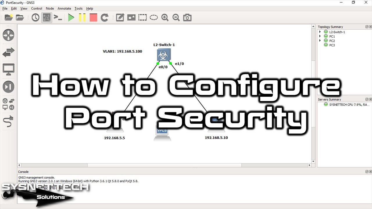
Before configuring Port-Security, add L2 Switch on Graphical Network Simulator-3. Also, in order to use a Virtual Computer, add VPCS to the workspace.
In this article, we will examine how to prevent the attack method mentioned by enabling Port Security on the Layer 2 Switch.
How to Configure Port Security in L2 Switch
Follow the steps below to enable the Port-Security on the Cisco L2 switch.
Step 1
After running GNS3, create a new project.

Step 2
Add one Layer 2 switch to the GNS3 workspace.

Step 3
Add 2 virtual computers VPCS to the GNS3 workspace.

Step 4
Right-click on Cisco Layer 2 Switch to add interfaces and improve performance.

Step 5
Click Configure from the options on the L2 Switch.

Step 6
Increase the RAM value of the L2 Switch as follows, and then click the HDD tab.

Step 7
Continue selecting SATA on the HDD tab. This option will enable Cisco Switch to perform more efficiently.

Step 8
Click the Network tab in the L2 Switch window, specify how many interfaces you will use in the Adapters section, and then click the OK button to save the settings.

Step 9
To cabling network devices in the GNS3 workspace, click cabling as in the image below.

Step 10
After wiring the devices in the workspace, click the Start All Nodes button.

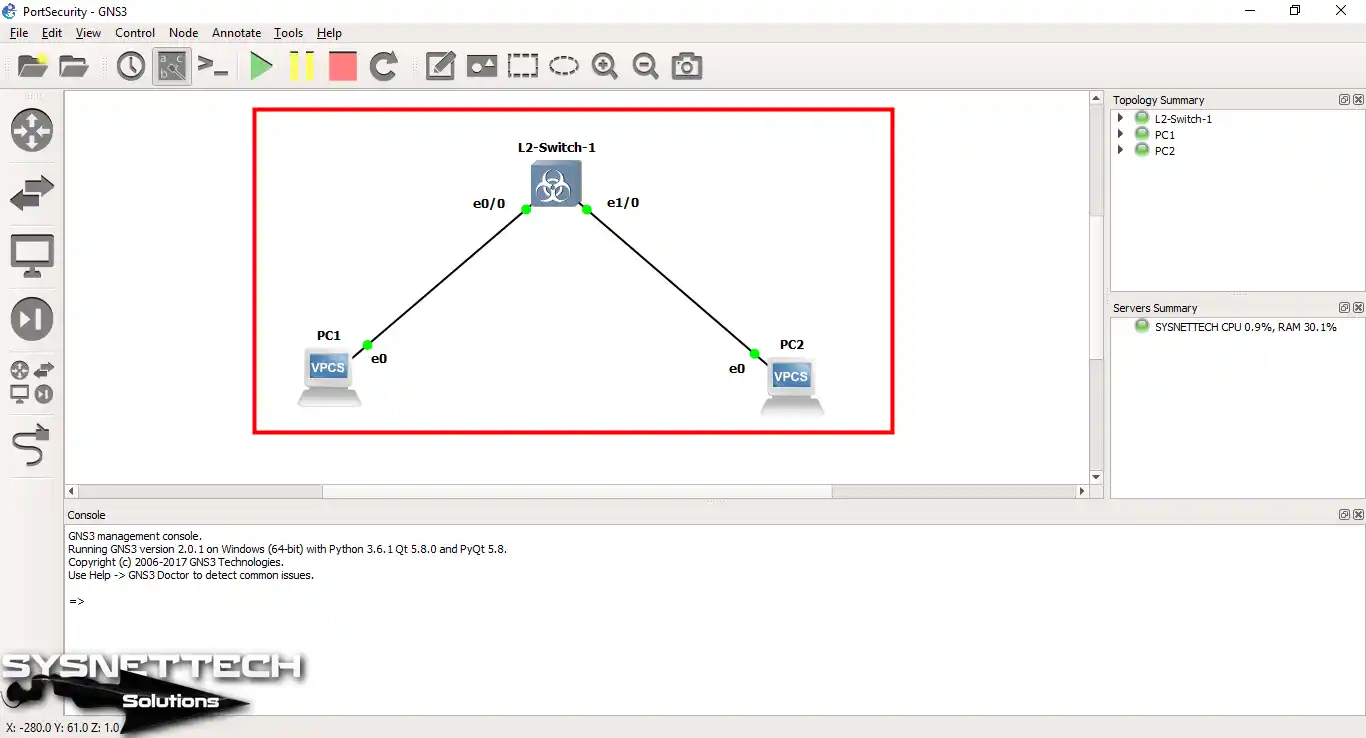
Step 11
The devices, such as the following image, should work correctly.
Step 12
You can enhance functionality by adding comments on the GNS3 workspace. Now run the console windows of all devices.

Step 13
To assign an IP address to VPCS PC1, execute the following command.
ip 192.168.5.5/24 192.168.5.1

Step 14
To assign an IP address to the VPCS PC2, execute the following command.
ip 192.168.5.10/24 192.168.5.1
After configuring VPCS PCs, check the TCP/IP settings using the show ip command.

Step 15
The connection test from PC1 to PC2 will be successful, as in the following image.

Step 16
The connection test from PC2 to PC1 will be successful, as in the following image.

Step 17
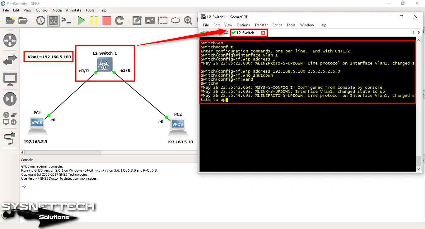
Use the following commands to assign an IP address to the VLAN1 on the Layer 2 Cisco Switch.
Switch#conf t
Enter configuration commands, one per line. End with CNTL/Z.
Switch(config)#interface vlan 1
*May 26 22:55:21.080: %LINEPROTO-5-UPDOWN: Line protocol on Interface Vlan1, changed s
Switch(config-if)#ip address 192.168.5.100 255.255.255.0
Switch(config-if)#no shutdown
Switch(config-if)#end
Switch#
Step 18
In this step, execute the commands below to enable this feature on the Switch.
If you only want to restrict the Port, you can change it in the violation section.
Switch#conf t
Enter configuration commands, one per line. End with CNTL/Z.
Switch(config)#interface gigabitethernet 0/0
Switch(config-if)#switchport host
switchport mode will be set to access
spanning-tree portfast will be enabled
channel group will be disabled

Switch(config-if)#switchport port-security
Switch(config-if)#switchport port-security mac-address sticky
Switch(config-if)#switchport port-security maximum 1
Switch(config-if)#switchport port-security violation shutdown
Switch(config-if)#exit
Switch(config)#
Switch(config)#
Switch(config)#interface gigabitethernet 0/1
Switch(config-if)#switchport host
switchport mode will be set to access
spanning-tree portfast will be enabled
channel group will be disabled

Switch(config-if)#switchport port-security
Switch(config-if)#switchport port-security mac-address sticky
Switch(config-if)#switchport port-security maximum 1
Switch(config-if)#switchport port-security violation shutdown
Switch(config-if)#end
Switch#wr
Set the Cisco Switch’s interface from Dynamic mode to Access mode with the “Switchport Host” command. Otherwise, the Cisco Switch interface will not be set to Access Port!

Step 19
By running the show port-security command in privileged mode on the Cisco Switch, you can check for any violations on the interfaces.
The SecurityViolation section will appear as 0 since no attacks are currently taking place.

Step 20
You can examine the port-related information and violations by applying the “show port-security interface gigabitethernet 0/0” command on the L2 Switch.

Step 21
After configuring PS, ping from PC1 to PC2 to test the connection between the PCs.

Step 22
Pinging from PC2 to PC1 will also be successful.

Step 23
After the Ping operation between computers, the MAC address table on the Cisco Switch is updated.
The switch has recorded the MAC addresses of PC1 and PC2 in the table and will compare them with the MAC addresses here in case of any violation.

Step 24
The test will also be successful if you Ping the IP address of the VLAN1 from the computers.
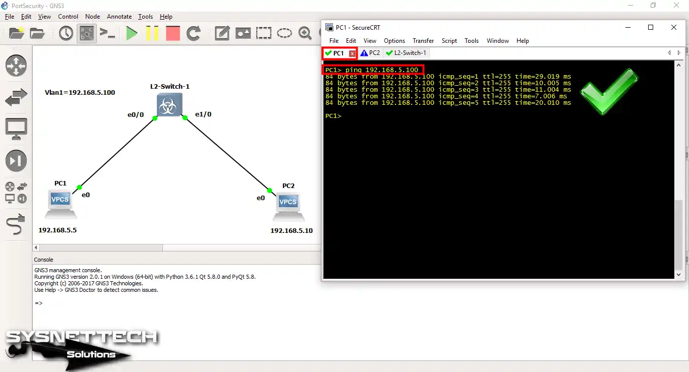
Step 25
Pinging from PC2 to VLAN1 will also be successful.

Step 26
After enabling PS, add another VPCS to the workspace to test whether this feature works.

Step 27
Configure the IP settings of the VPCS PC3 as follows.

Step 28
Now, right-click to remove the cable between PC1 and L2 Switch and click Delete.

Step 29
Click the wiring option to connect the VPCS PC3 to the L2 Switch.

Step 30
When you click L2 Switch, select the Ethernet0/0 interface.
In this interface, PC1 was connected, and check what happens when you connect PC3 to it.

Step 31
When you ping from PC3 to PC2, you will receive the host unreachable message as follows.

Step 32
Since there is a violation in the switch’s console, log records will appear as follows;
Switch#
*May 26 23:03:58.687: %PM-4-ERR_DISABLE: psecure-violation error detected on Gi0/0, putting Gi0/0 in err-disable state
*May 26 23:03:58.697: %PORT_SECURITY-2-PSECURE_VIOLATION: Security violation occurred, caused by MAC address 0050.7966.6802 on port GigabitEthernet0/0.
*May 26 23:03:59.687: %LINEPROTO-5-UPDOWN: Line protocol on Interface GigabitEthernet0/0, changed state to down
*May 26 23:04:00.693: %LINK-3-UPDOWN: Interface GigabitEthernet0/0, changed state to down
Switch#
In the log above, you can see that there is a security breach on GigabitEthernet0/0.
Immediately after this notification, the Switch will close the corresponding port.

Step 33
When you run the show port-security command on the Layer 2 Switch, check for a violation on Gig0/0.

Step 34
Likewise, when you check the interface states by running the show ip interface brief command on the L2, you can see that the GigabitEthernet0/0 interface is closed.

Step 35
PC3 could not access the network environment due to port security. Unplug the cable to connect the PC1 computer to the L2 Switch again.

Step 36
Reconnect the PC1 to interface 0/0 on the L2 Switch.

Step 37
Since the Cisco Switch closes the Gig0/0 interface, you must re-enable it. To re-activate this interface, run shutdown, and then there will be no shutdown.
Switch successfully defended itself by shutting down the interface. If the Violation option had been set to Restrict, the interface would not have been closed.

Step 38
When you rerun the show port-security command, you can see that the violation part is empty.

Step 39
You can see that PC1 accessed the network environment successfully again!

Show Commands Related to Port Security
Switch#show port-security
Secure Port MaxSecureAddr CurrentAddr SecurityViolation Security Action
(Count) (Count) (Count)
---------------------------------------------------------------------------
Gi0/0 1 0 0 Shutdown
Gi0/1 1 0 0 Shutdown
---------------------------------------------------------------------------
Total Addresses in System (excluding one mac per port) : 0
Max Addresses limit in System (excluding one mac per port) : 4096
Switch#
Switch#show port-security interface gigabitethernet 0/0
PS: Enabled
Port Status : Secure-up
Violation Mode : Shutdown
Aging Time : 0 mins
Aging Type : Absolute
SecureStatic Address Aging : Disabled
Maximum MAC Addresses : 1
Total MAC Addresses : 0
Configured MAC Addresses : 0
Sticky MAC Addresses : 0
Last Source Address:Vlan : 0000.0000.0000:0
Security Violation Count : 0
Switch#
Switch#show mac address-table
Mac Address Table
-------------------------------------------

Vlan Mac Address Type Ports
---- ----------- -------- -----
1 0050.7966.6800 STATIC Gi0/0
1 0050.7966.6801 STATIC Gi0/1
Total Mac Addresses for this criterion: 2
Switch#
Switch# *May 26 23:03:58.687: %PM-4-ERR_DISABLE: psecure-violation error detected on Gi0/0, putting Gi0/0 in err-disable state *May 26 23:03:58.697: %PORT_SECURITY-2-PSECURE_VIOLATION: Security violation occurred, caused by MAC address 0050.7966.6802 on port GigabitEthernet0/0. *May 26 23:03:59.687: %LINEPROTO-5-UPDOWN: Line protocol on Interface GigabitEthernet0/0, changed state to down *May 26 23:04:00.693: %LINK-3-UPDOWN: Interface GigabitEthernet0/0, changed state to down Switch#
Switch#show port-security
Secure Port MaxSecureAddr CurrentAddr SecurityViolation Security Action
(Count) (Count) (Count)
---------------------------------------------------------------------------
Gi0/0 1 1 1 Shutdown
Gi0/1 1 1 0 Shutdown
---------------------------------------------------------------------------
Total Addresses in System (excluding one mac per port) : 0
Max Addresses limit in System (excluding one mac per port) : 4096
How to Enable Port-Security ⇒ Video
You can watch the video below to activate Port-Security and also subscribe to our YouTube channel to support us!
Conclusion
In this article, we have completed the Port Security configuration on L2 Switch. When implementing it in the actual scenario, you should configure MAC addresses as Static. Thanks for following us!

Be the first to share your comment