
In this article, I will explain how to configure EIGRP on Cisco Routers with the GNS3 emulator software. This protocol, which Cisco specifically owns, manages network traffic efficiently and effectively. I will also cover the processes of setting up a network topology in your virtual environment, configuring routers, and adding virtual machines.
However, after enabling this protocol, I will examine the show commands to test the network connection. If you create a correct virtual network, these commands will be helpful. In addition, you can use Wireshark to check the functionality of this protocol. Now, let’s start by explaining how to configure EIGRP with GNS3!

How to Set Up EIGRP Routing on a Cisco Router with GNS3 Emulator?
EIGRP is a proprietary routing protocol created by Cisco. In addition, unlike other protocols, it only sends updates when there is a network change. This reduces unnecessary network traffic and provides more efficient routing.
Enhanced Interior Gateway Routing Protocol only works with Cisco devices. As a result, we cannot enable it on other branded devices. Plus, when installing it, we also need to configure an AS (Autonomous System) number. In short, we can do this with the “router eigrp (AS Number)” command.
In addition, you need to add the connected networks to the Router. To learn more about this protocol, I have previously shared an article with you about what EIGRP is.
Now, in this article, let’s configure the EIGRP protocol valid on Cisco devices in the GNS3 simulator!
Things We Need to Do Before EIGRP Topology
There are a few essential steps before configuring EIGRP with GNS3. Let me briefly state that GNS3 is ideal for simulating various network experiments by designing complex network topologies. However, there are things you need to do before configuring a protocol like this.
First, it is enough to create a basic network topology with two Cisco Routers, a Switch, and a PC on GNS3. You can drag the necessary devices from the devices menu and drop them into the topology area. The visual design you make for yourself will make your work more comfortable.
Then, of course, you should add IP addresses to communicate with your network devices. You can successfully create your EIGRP topology by building your network with the correct logic.
In addition, you should make sure that your GNS3 Routers support EIGRP, of course. Still, even old Cisco devices support this protocol. You should still make sure that your device supports it.
How to Create a New Topology for EIGRP on GNS3
Before proceeding with the configuration steps, perform the GNS3 and VMware integration process. Then, follow the steps below to enable EIGRP.
Step 1
As the first step, run the GNS3 network simulator software. Then, create a new project, as you will create a new topology for the routing protocol.

Step 2
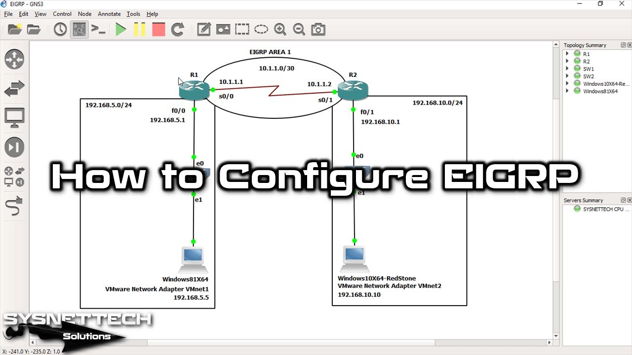
Create a network design for EIGRP topology, as shown in the image below. Then, run GNS3 Routers and open the CLI command prompts.

Step 3
Configure the Cisco Router R1 interfaces you added to your topology with the following commands.
R1#conf t
Enter configuration commands, one per line. End with CNTL/Z.
R1(config)#interface fastethernet 0/0
R1(config-if)#ip address 192.168.5.1 255.255.255.0
R1(config-if)#no shutdown
R1(config-if)#exit
R1(config)#
*Mar 1 00:00:43.715: %LINK-3-UPDOWN: Interface FastEthernet0/0, changed state to up
*Mar 1 00:00:44.715: %LINEPROTO-5-UPDOWN: Line protocol on Interface FastEthernet0/0, changed state to up
R1(config)#
R1(config)#interface serial 0/0
R1(config-if)#ip address 10.1.1.1 255.255.255.252
R1(config-if)#no shutdown
R1(config-if)#end
R1#

Step 4
You should also configure the Cisco Router R2 interfaces in the same way. But before I forget, do not mix fastethernet and serial interfaces here.
R2#conf t
Enter configuration commands, one per line. End with CNTL/Z.
R2(config)#interface fastethernet 0/1
R2(config-if)#ip address 192.168.10.1 255.255.255.0
R2(config-if)#no shutdown
R2(config-if)#exit
R2(config)#
*Mar 1 00:02:07.995: %LINK-3-UPDOWN: Interface FastEthernet0/1, changed state to up
*Mar 1 00:02:08.995: %LINEPROTO-5-UPDOWN: Line protocol on Interface FastEthernet0/1, changed state to up
R2(config)#
R2(config)#interface serial 0/1
R2(config-if)#ip address 10.1.1.2 255.255.255.252
R2(config-if)#no shutdown
R2(config-if)#end
R2#

Adding VMware Virtual Machines to Topology
Step 1
After starting the virtual machines, you need to configure the VMnet settings. I am configuring them because I am using Windows 10 and 8 versions in my virtual topology.
You can use it on a Windows or Linux virtual PC if you want. If you prefer to continue with the example topology, you should configure the network cards of your VMs.
Now, select VMnet1 for the network card of the Windows 8.1 VM, as in the example, and start the virtual machine.

Step 2
Configure VMnet2 as the network card of your Windows 10 virtual machine.

Step 3
You have configured the TCP/IP settings of your Windows 8.1 virtual computer. Now test the connection by pinging the Router FastEthernet 0/0 and Serial 0/0 interfaces from this system.
Also, before configuring the protocol, ping the Router R2 interfaces. This way, you can see how they work without a routing protocol between them.

Step 4
Perform the same operations, i.e., connection test, on the Windows 10 VM.
Enabling EIGRP on Cisco Routers
Step 1
We will communicate with two different networks using this routing protocol. To do this, open the R1 CLI command prompt and apply the commands below in the CLI.
However, make sure to use the Wild Card Mask when defining networks in this protocol.
R1#conf t
Enter configuration commands, one per line. End with CNTL/Z.
R1(config)#
R1(config)#router eigrp 1
R1(config-router)#network 10.1.1.0 ?
A.B.C.D E-I-G-R-P wild card bits

R1(config-router)#network 10.1.1.0 0.0.0.3
R1(config-router)#network 192.168.5.0 0.0.0.255
R1(config-router)#end
R1#

Step 2
On the Cisco Router R2 device, execute the following commands at the CLI command prompt.
R2#conf t
Enter configuration commands, one per line. End with CNTL/Z.
R2(config)#
R2(config)#router eigrp 1
R2(config-router)#network 10.1.1.0 0.0.0.3
R2(config-router)#network 192.
*Mar 1 00:26:14.107: %DUAL-5-NBRCHANGE: IP-E-I-G-R-P(0) 1: Neighbor 10.1.1.1 (Serial0/1) is up: new adjacency
R2(config-router)#network 192.168.10.0 0.0.0.255
R2(config-router)#end
R2#

Step 3
If everything is OK, run the show ip route command on R1. At this point, you will see that the routing protocol is active, as shown in the image below.

Step 4
Check the current settings on GNS3 Router R2 with the show ip route command.

Step 5
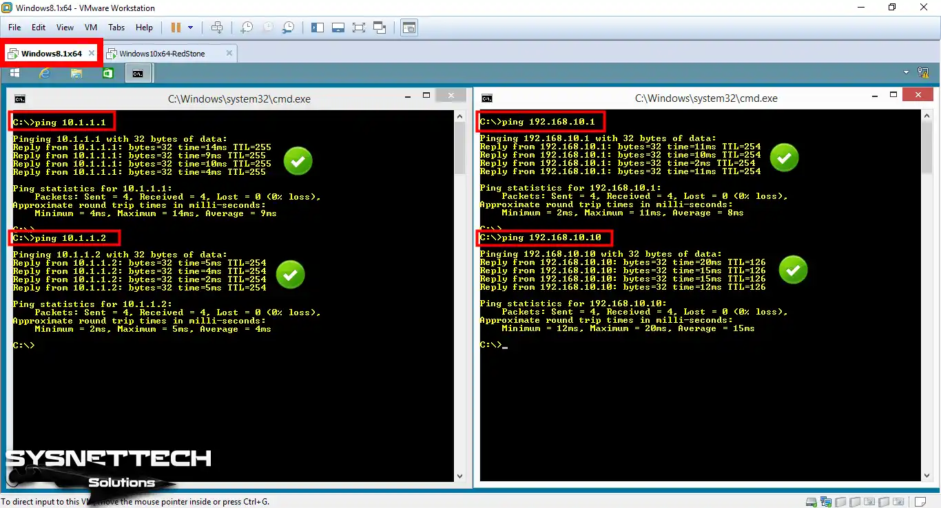
We have configured EIGRP with GNS3. Now, let’s go back to our VMware virtual systems. For example, ping both your Router and the serial interface of the device on the other network from the Windows 8 VM.
Also, ping the PC with the IP address 192.168.10.10 on the 192.168.10.0/24 network. At this stage, make sure they are pinging each other, as in the image below.
Step 6
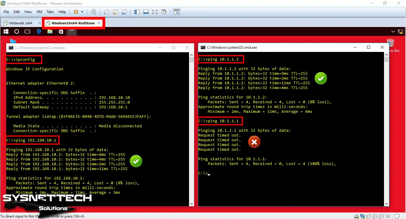
As you did in the previous step, this time, switch to your Windows 10 VM. From here, test the connection to the fastethernet and serial interfaces using the ping command.
Also, this time, check that you can access PC1 from PC2.

How to Verify EIGRP Settings on the Router
Step 1
Now that our topology is OK, let’s test the Advanced Interior Gateway Routing Protocol. So, without wasting any time, execute the show commands below in R1’s CLI.

Step 2
As I mentioned above, this time, observe the show command output on GNS3 Router R2.

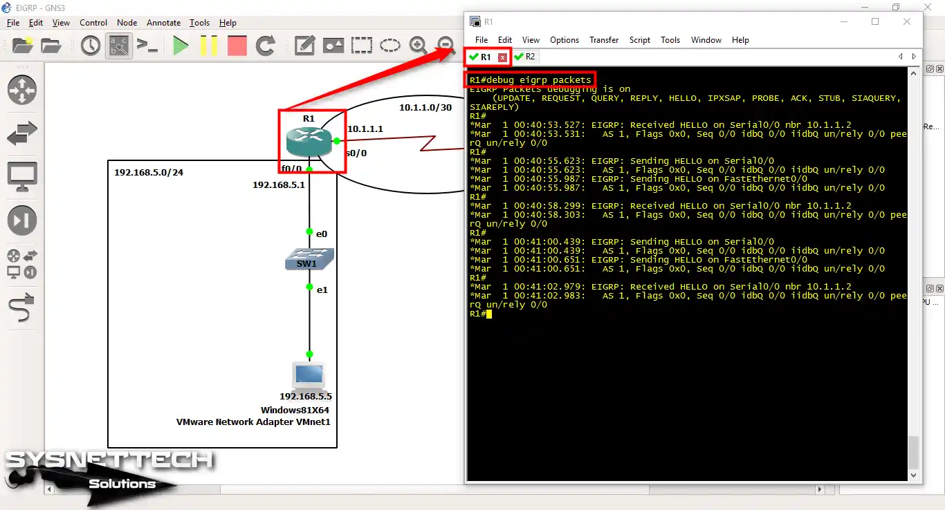
Step 3
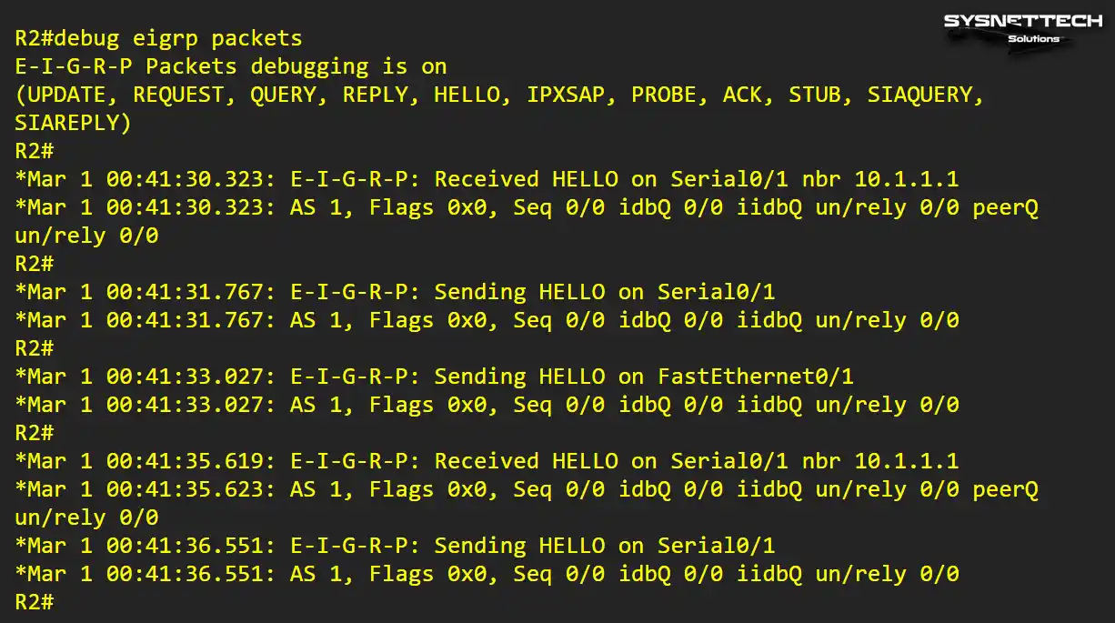
Now, to verify this protocol, execute the debug eigrp packets command.
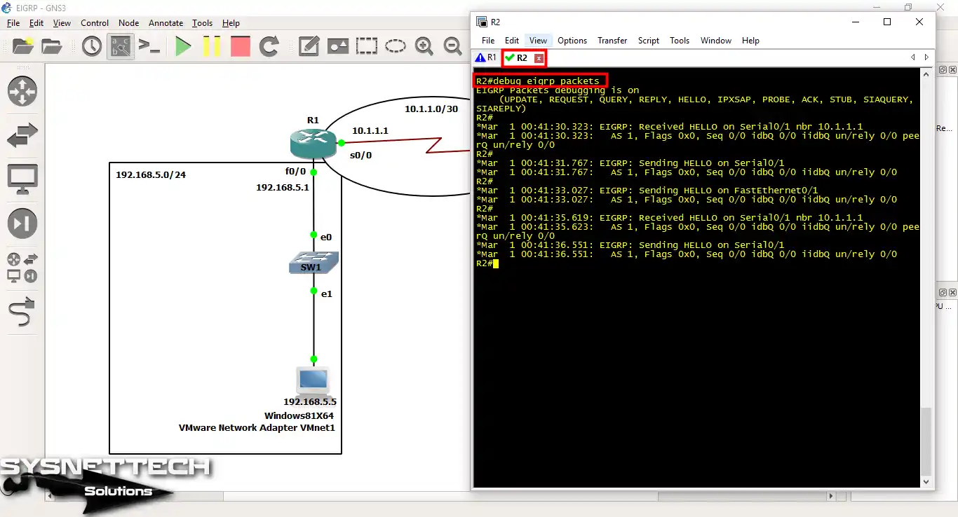
Step 4
Apply the Debug command on R2 this time. Then, check that Hello packets are logged between the GNS3 Routers.
EIGRP Authentication with Wireshark
Step 1
There are other ways to verify the advanced routing configuration. For example, you can use the Wireshark network analyzer program.
To do this, install Wireshark on your PC. Then, Right Click / Start Capture on the Serial cable that connects the Routers.

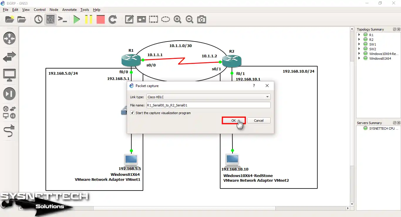
Step 2
When you open the Packet Capture window, check the Link Type value. If it says Cisco HDLC, there is no problem. After that, enable “Start the capture visualization program” and click OK.
Step 3
As soon as you click the OK button, GNS3 will open the Wireshark program. Thus, you will start to see EIGRP packets in your analysis software.
For example, when you look at the image below, you will see Hello packets. Here, you can understand that Hello packets are carried from the 224.0.0.10 Multicast address.

Show Commands to Check EIGRP Configuration
You can verify EIGRP settings on both GNS3 and Cisco Routers. Here are the show commands we use most often:
- show ip route: This command shows us the routes that devices have learned via this advanced routing protocol. Plus, it allows us to examine the routing table of the current devices.
- show ip eigrp neighbors: As we can understand from its name, this command provides information about neighbors. That is, we can learn the IP addresses, interfaces, and uptimes of neighboring devices.
- show ip eigrp interfaces: We learn the status of the interfaces on the Router to which we apply this command. In short, we obtain configuration and operational information.
- show ip eigrp topology: This command shows us the Router’s routing table and related metrics. We can also check which devices in the local network create a topology with, that is, the target device.
- show ip eigrp traffic: This command shows us statistics about EIGRP traffic, such as the number of packets sent and received between routers.
In short, we need to check if EIGRP is working correctly on Cisco routers. For example, I have added some screenshots from the topology I created in the GNS3 emulator for you.
- R1# show ip route

- R2# show ip route

- R1# debug eigrp packets

- R2# debug eigrp packets
- R1# show running-config

- R2# show running-config

Configuring Enhanced Interior Gateway Routing Protocol with GNS3 ⇒ Video
Watch our video tutorial below to enable and verify the Cisco routing protocol. However, if you found the content helpful, please join to our YouTube channel to show your cooperation!
Frequently Asked Questions (FAQ) About
- How to enable EIGRP on a Cisco Router?
- What are the basic configuration steps?
- How do I define network interfaces?
- What are the basic parameters?
- How do I verify the EIGRP configuration?
- How do I access the CLI command line?
Conclusion
As a result, we have successfully set up EIGRP routing using the GNS3 platform. Also, by following the steps in this topology, we have achieved effective communication between two networks. I have shown its practical application in terms of configuring this protocol and testing network connections.
However, do not forget to write the Wildcard Mask address correctly. If this is wrong, EIGRP will not work correctly.
In addition, I have examined the show commands and packet capture with Wireshark. Thus, we have made sure that the network is working correctly. If you use these verification methods, you can better evaluate the performance of your topology.
In conclusion, I hope this article will help you with the Cisco routing protocol. Thank you for your interest and following our guide!

Be the first to share your comment