
In this article, I will show you how to configure a Cisco Switch device using GNS3 as a foundation. First, I will show the setup steps by making a simple network layout.
Then, I will include how to build the network topology and configure VLANs in this process. Next, we will assign IP addresses and manage the switch correctly.
Also, I will put VMware VMs in the plan to make the Switch work better. In brief, we will do a simple setup of the Switch in a real network case.
Understanding Cisco Switches for CCNA Candidates
Before we start with the topology, I should say that Switches have two main types. The first is Layer 2 devices, and the other is Layer 3. These work at the Data Link layer of the OSI model.
Switches help PCs talk using MAC address lists. They also work with VLANs, letting us split our networks in theory. That is, it means we can arrange our network without changing the real wires.
In a normal network, computers send data inside MAC frames. Layer 2 Switches handle these frames smartly. They build and keep MAC address tables.
These tables link MAC addresses to port numbers. This work cuts down on needless network broadcasts. So, both our network speed and usefulness get better. In brief, they send data only to the right target.
I guess you are getting ready for the Cisco CCNA (Cisco Certified Network Associate) exams. If so, you can use tools like GNS3 and Cisco Packet Tracer.
These simulation programs let you set up and test Cisco network devices. Thus, you try different network setups yourself.
Because of this, you can do real practice work without physical hardware. These programs help you get better at knowing network ideas.
Also, by building your device setup skills, you make the first move toward passing the CCNA tests.
How to Configure a Cisco Switch with GNS3
The surest way to set up a Cisco Switch is to use GNS3 software. With this strong tool, you can work with network devices like they were real.
Furthermore, its clear screen helps you get better at managing networks. In brief, you can study and learn complex setups better. Thus, you test different network topologies well.
1. Configure Switch Ports, Security & VLAN
Step 1
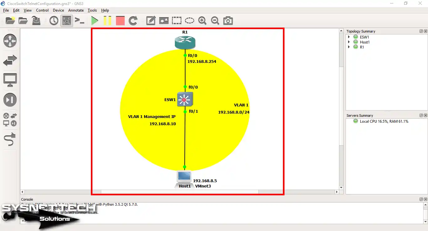
To start, open the GNS3 program and make a new project for the simple setup. Then, get the topology ready, as you see below.
In this topology, I used a Layer 3 Switch that functions at the OSI Network layer.
Step 2
We often set up the Switch setup with a computer. However, you should use Telnet for faraway use. This way, you do not need to be near the machine.
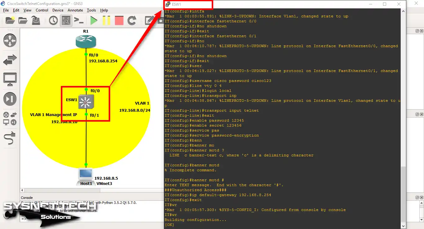
Now, follow the steps below to first determine the Switch’s hostname. Next, set up the Telnet part. Finally, type the enter commands to keep the passwords safe.
ESW1# conf t
ESW1(config)# hostname IT
IT# conf t
IT(config)# interface fastethernet 0/0
IT(config-if)# no shutdown
IT(config-if)# exit
IT(config)# interface fastethernet 0/1
IT(config-if)# no shutdown
IT(config-if)# exit
IT(config)# username cisco password cisco123
IT(config)# line vty 0 4
IT(config-line)# login local
IT(config-line)# transport input telnet
IT(config-line)# exit
IT(config)# enable password 12345
IT(config)# enable secret 123456
IT(config)# service password-encryption
IT(config)# banner motd #
Enter TEXT message. End with the character '#'.
###Unauthorized Access###
IT(config)# ip default-gateway 192.168.8.254
IT(config)# end
IT# wr
To assign an IP address to switches, you must first configure the VLAN interface. For example, if you want to assign an IP address to the default VLAN1, please use the following command.
IT# conf t
IT(config)# interface vlan1
IT(config-vlan)# ip address 192.168.8.10 255.255.255.0
IT(config-vlan)# no shutdown
IT(config-vlan)# end
IT# wr
2. Check Your Virtual System’s IP Value
Step 1
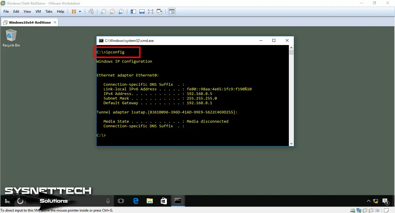
Add the virtual machine to your network topology and run it. Then, type the “ipconfig” command in the CMD command prompt and run it. This will allow you to check your TCP/IP settings. If these settings do not work with the topology, set up the VM like this.
Step 2
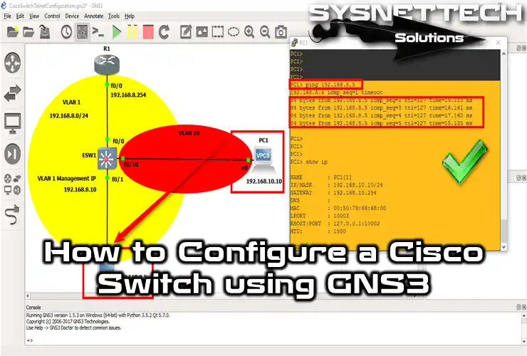
Now it’s time to test your connection. Ping the VLAN management interface from your VMware virtual machine. This will let you check that the link is working correctly.
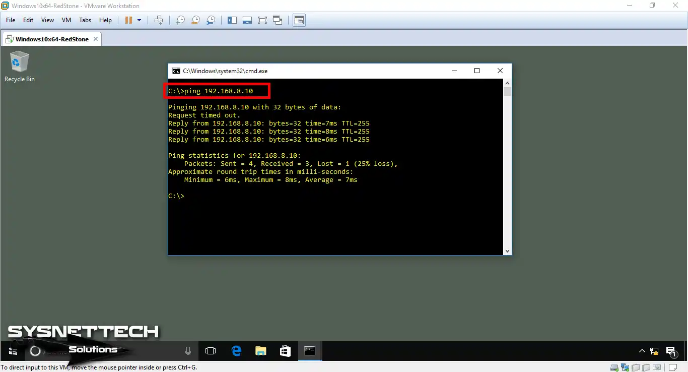
Step 3
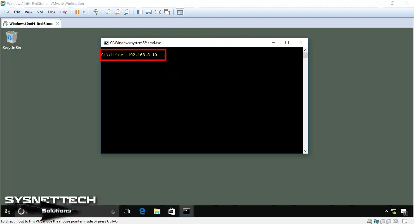
Open CMD to connect to Switch VLAN1 from your virtual machine. Then, simply make the faraway control link by using the “telnet 192.168.10.10” command.
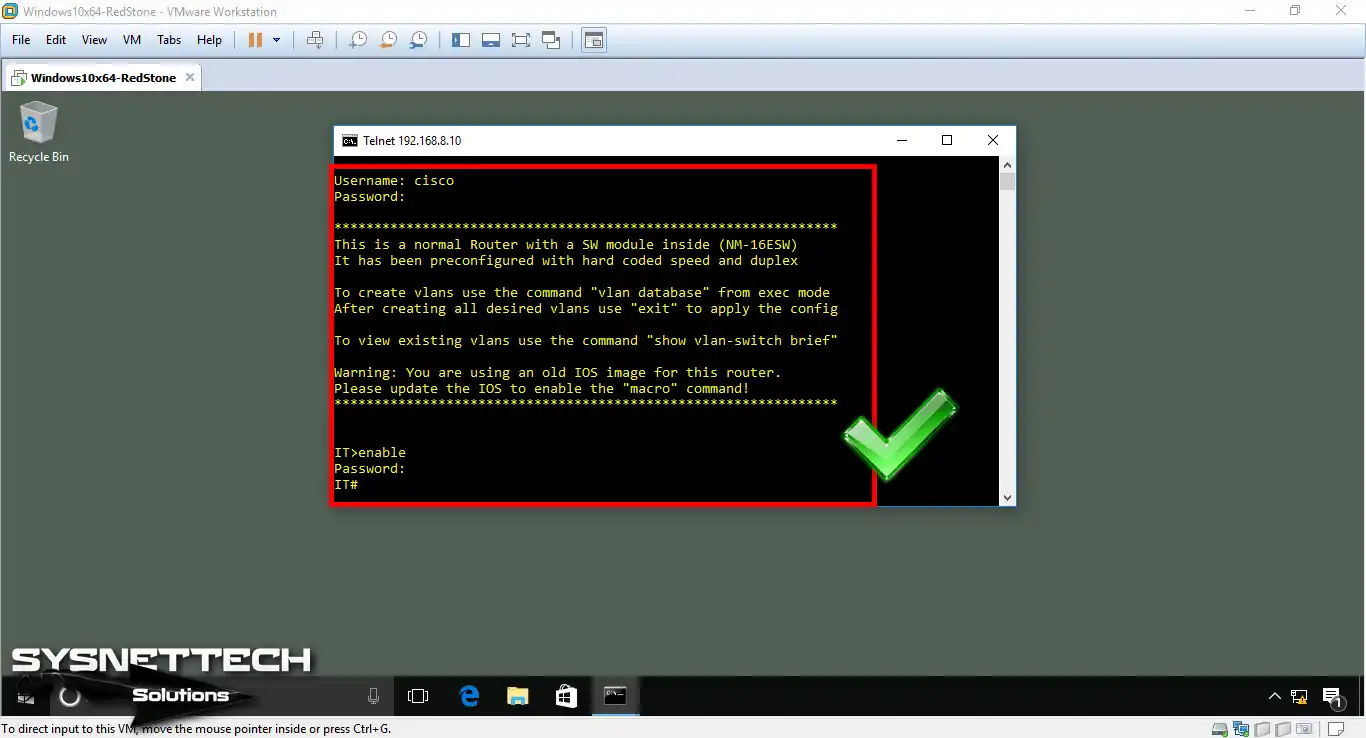
Step 4
In Step 2, we created a new user for the Switch. Now, type the user name and password you made for the telnet connection.
3. Create a New VLAN on the Cisco Switch
VLANs let us make network group control better. That is, by segmenting the network, we can separate traffic for various teams in a company.
For example, the accounting and IT teams can work apart. This method can improve safety by controlling access between groups.
Also, we make things faster by cutting down on broadcast traffic. Key point: routing between VLANs allows good talk and keeps private data safe.
Therefore, let’s create a VLAN in terms of Cisco Switch basic settings!
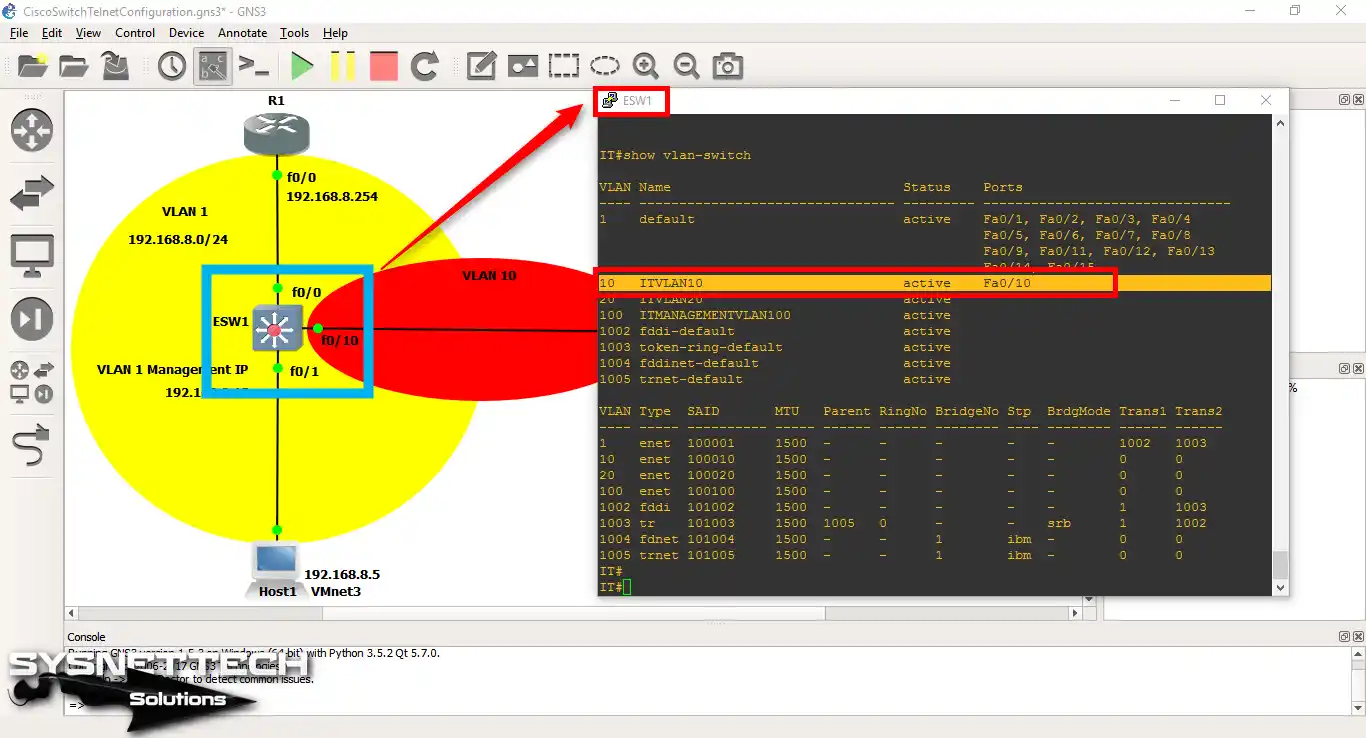
Step 1
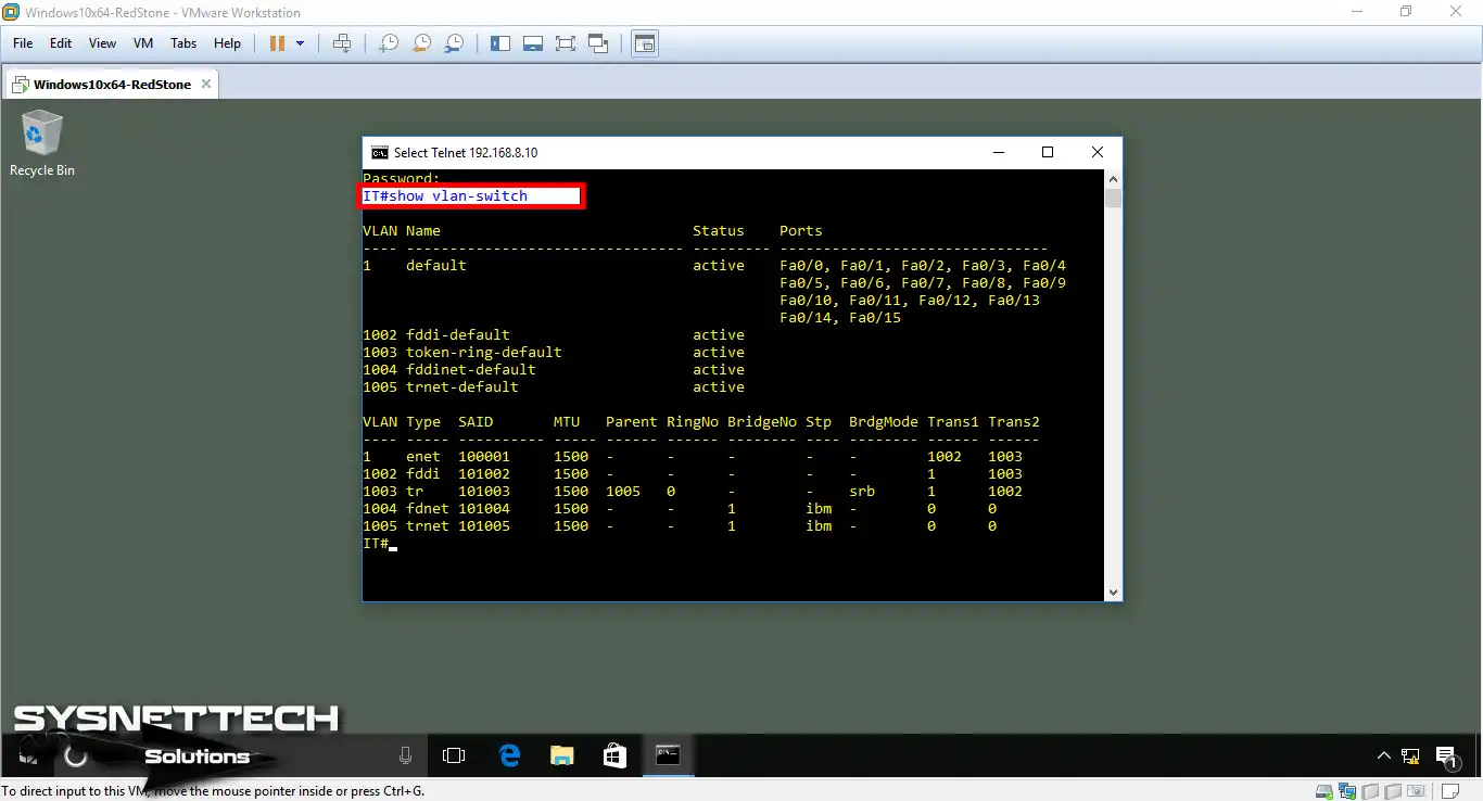
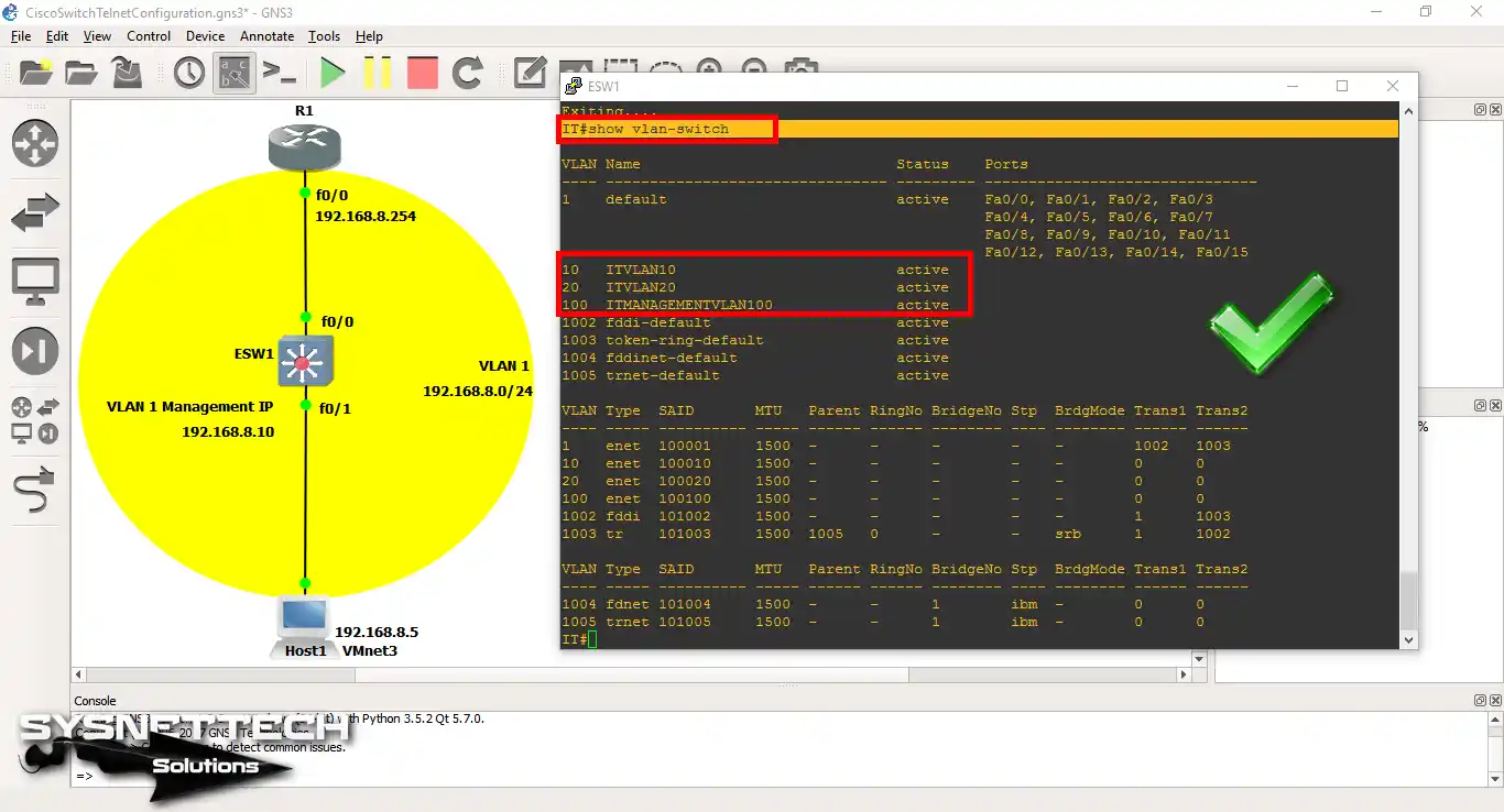
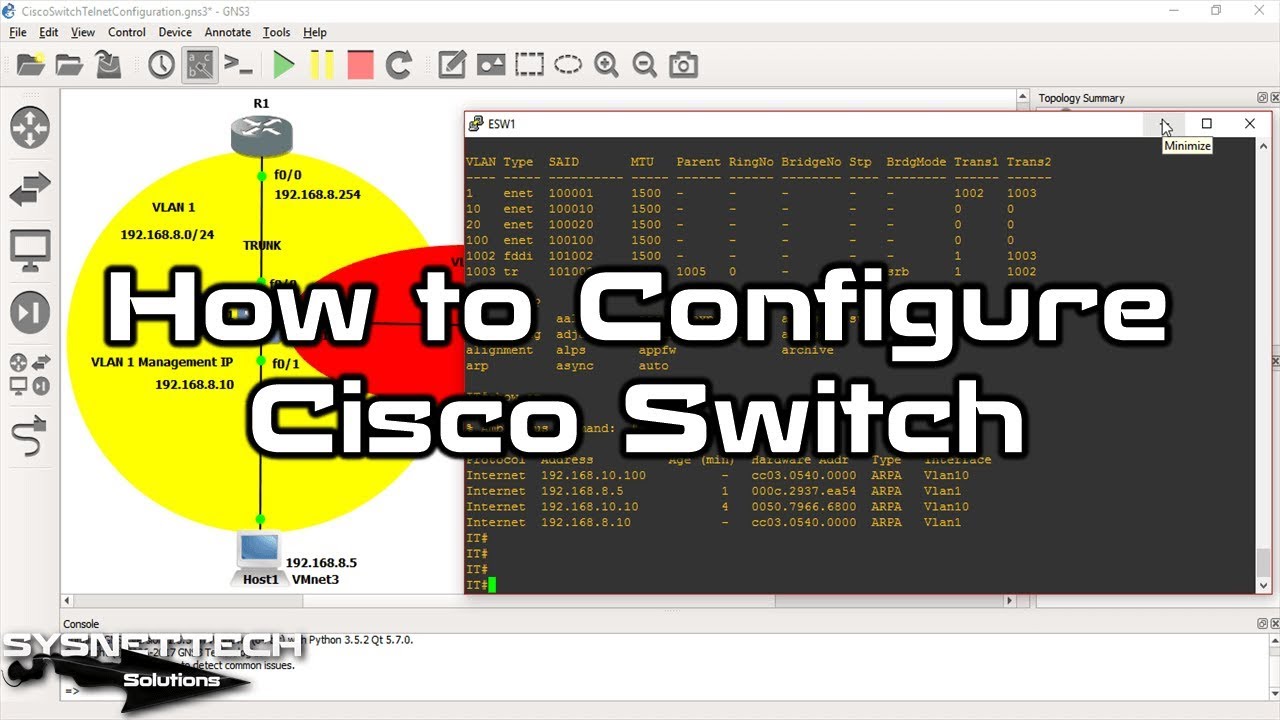
Use the “show vlan-switch” command in the Switch’s privileged mode. So, you can check the current VLAN structure easily.
When you examine the image, you can see that the default VLAN number is 1.
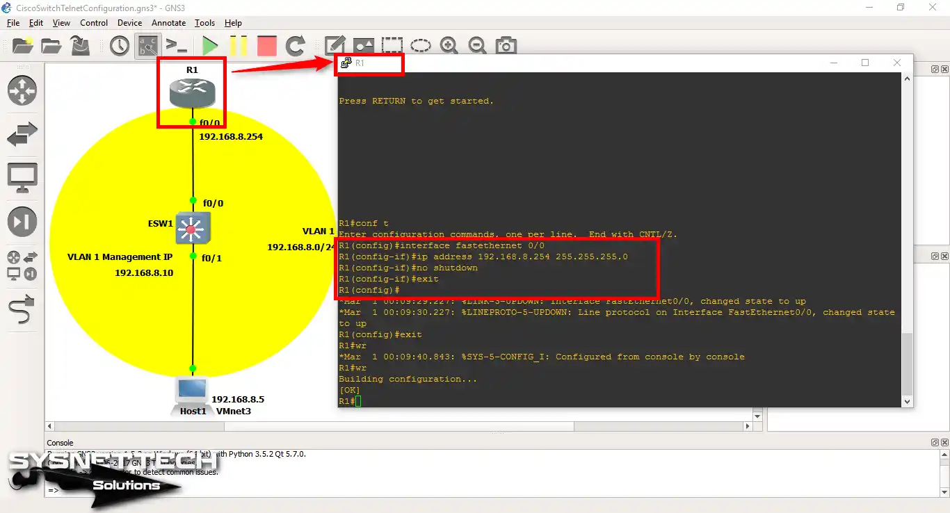
Step 2
Now, open the Cisco Router’s CLI command box. Right after, set up the FastEthernet 0/0 port with the commands below. And in the last step, turn on the port with “no shutdown”.
R1# conf t
R1(config)# interface fastethernet 0/0
R1(config-if)# ip address 192.168.8.254 255.255.255.0
R1(config-if)# no shutdown
R1(config-if)# exit
R1(config)# exit
R1# wr
Step 3
Ping the Router’s FastEthernet0/0 port from your virtual PC. Right after this step, you can see that you have made a good link.

Step 4
Now, after starting the CLI screen to make a VLAN on the Switch, use the following commands in order.
In addition, make sure you are in Switch’s privileged mode.
IT# vlan database
IT(vlan)# vlan 10 name ITVLAN10
VLAN 10 added:
Name: ITVLAN10
IT(vlan)# vlan 20 name ITVLAN20
VLAN 20 added:
Name: ITVLAN10
IT(vlan)# vlan 100 name ITMANAGEMENTVLAN100
VLAN 100 added:
Name: ITMANAGEMENTVLAN100
IT(vlan)# exit
APPLY completed.
Exiting....
IT#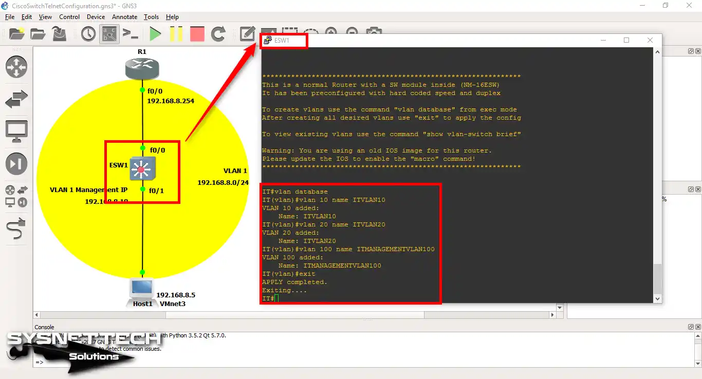
Step 5
Run the “show vlan-switch” command in the CLI console. This method allows you to check all the VLANs you have created easily.
4. Add VPCS to Your GNS3 Topology
Step 6
Add one VPCS to the GNS3 workspace as shown below. Connect the VPCS you added to the Switch’s FastEthernet0/10 interface.
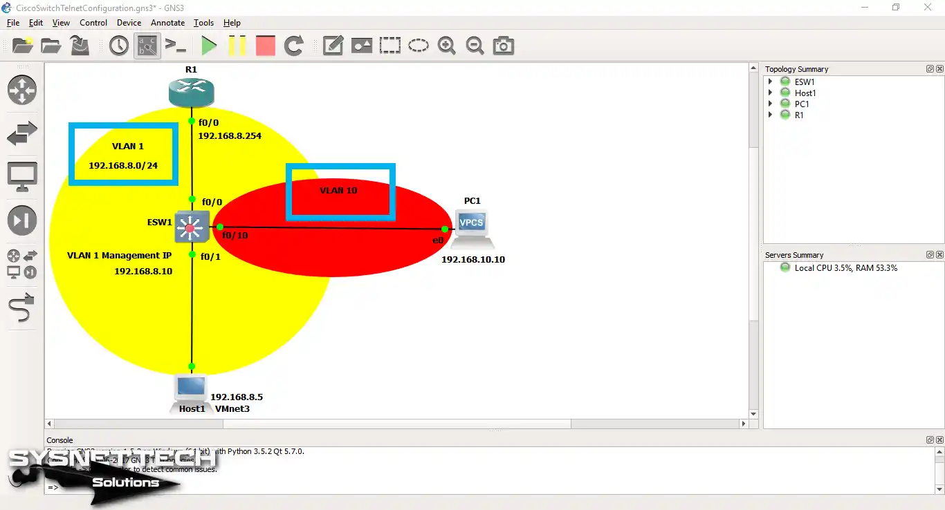
Step 7
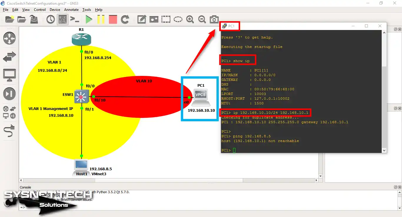
As soon as you open the PC1 CLI console, assign an IP address to the VPCS.
5. Make the Virtual PC a Member of the VLAN
To add the VPCS to a VLAN, you must first configure the port that connects it to the VLAN.
Connect the VPCS to the Switch’s FastEthernet0/10 interface. Then, run the “switchport access vlan 10” command to add the relevant port to VLAN 10.
Devices that are members of all VLANs must also be able to communicate with each other. To achieve this, you must configure the interface connected to the Cisco Router as a TRUNK.
IT# conf t
IT(config)# interface fastethernet 0/10
IT(config-if)# switchport mode access
IT(config-if)# switchport access vlan 10
IT(config-if)# exit
IT(config)# interface fastethernet 0/0
IT(config-if)# switchport mode trunk
IT(config-if)# exit
IT(config)# end
IT# wr
6. Configure Inter-VLAN on the Router
Step 1
Create a subinterface on the router for VLAN communication.
As you can see in the commands below, you have created the 0/0.1 and 0/0.10 subinterfaces. Remember that you can change these values. Here, I made sub-ports based on the VLAN numbers.
R1# conf t
R1(config)# interface fastethernet 0/0
R1(config-if)# no ip address
R1(config-if)# exit
R1(config)# interface fastethernet 0/0.1
R1(config-if)# ip address 192.168.8.254 255.255.255.0
R1(config-if)# encapsulation dot1Q 1
R1(config-if)# exit
R1(config)# interface fastethernet 0/0.10
R1(config-if)# ip address 192.168.10.254 255.255.255.0
R1(config-if)# encapsulation dot1Q 10
R1(config-if)# exit
R1(config)# end
R1# wr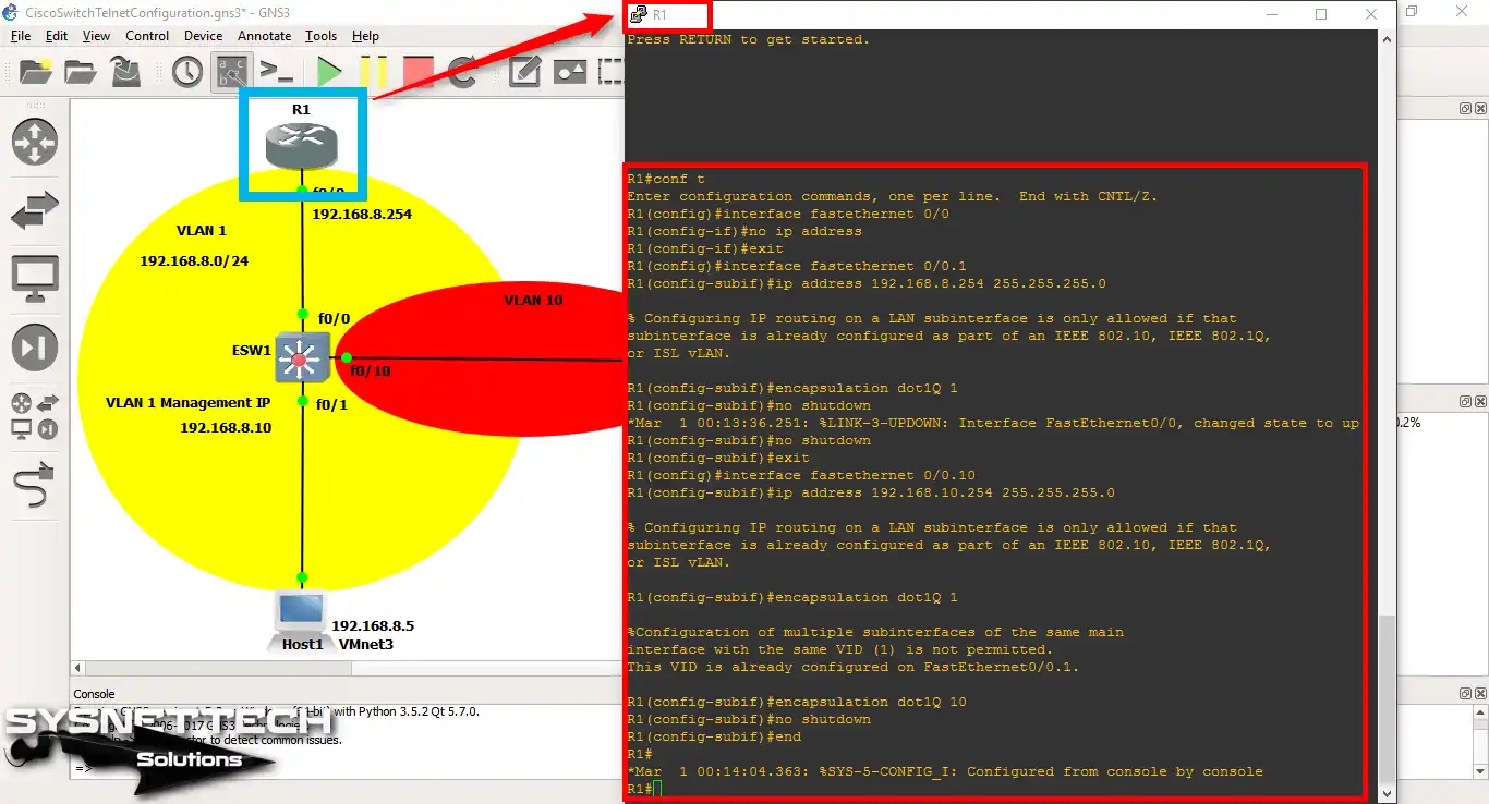
Step 2
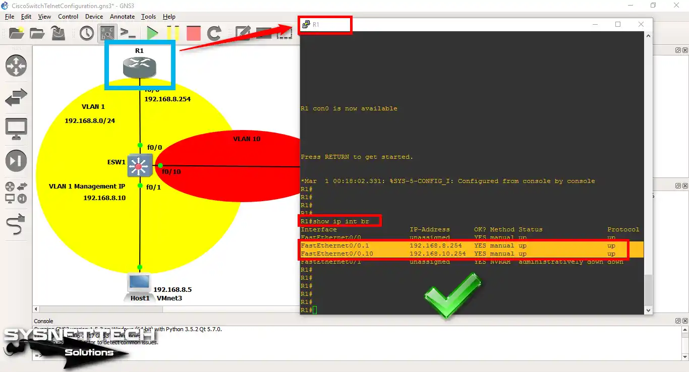
Now, check the ports on the Cisco Switch using the “show vlan-switch” command.
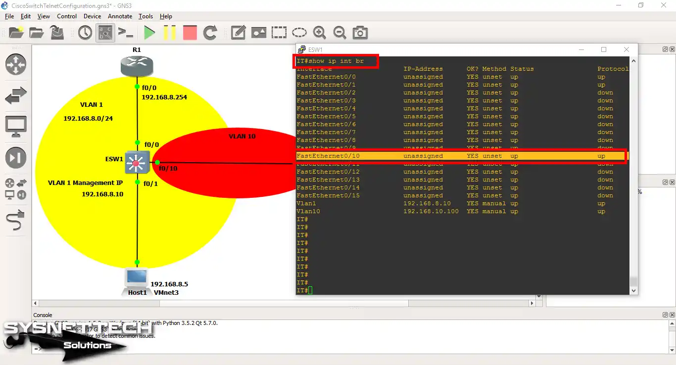
Step 3
This time, run the “show ip interface brief” command. This allows you to check the status of all Switch interfaces. You can also clearly see that the ports are open.
Step 4
You can also check Router ports with the same command.
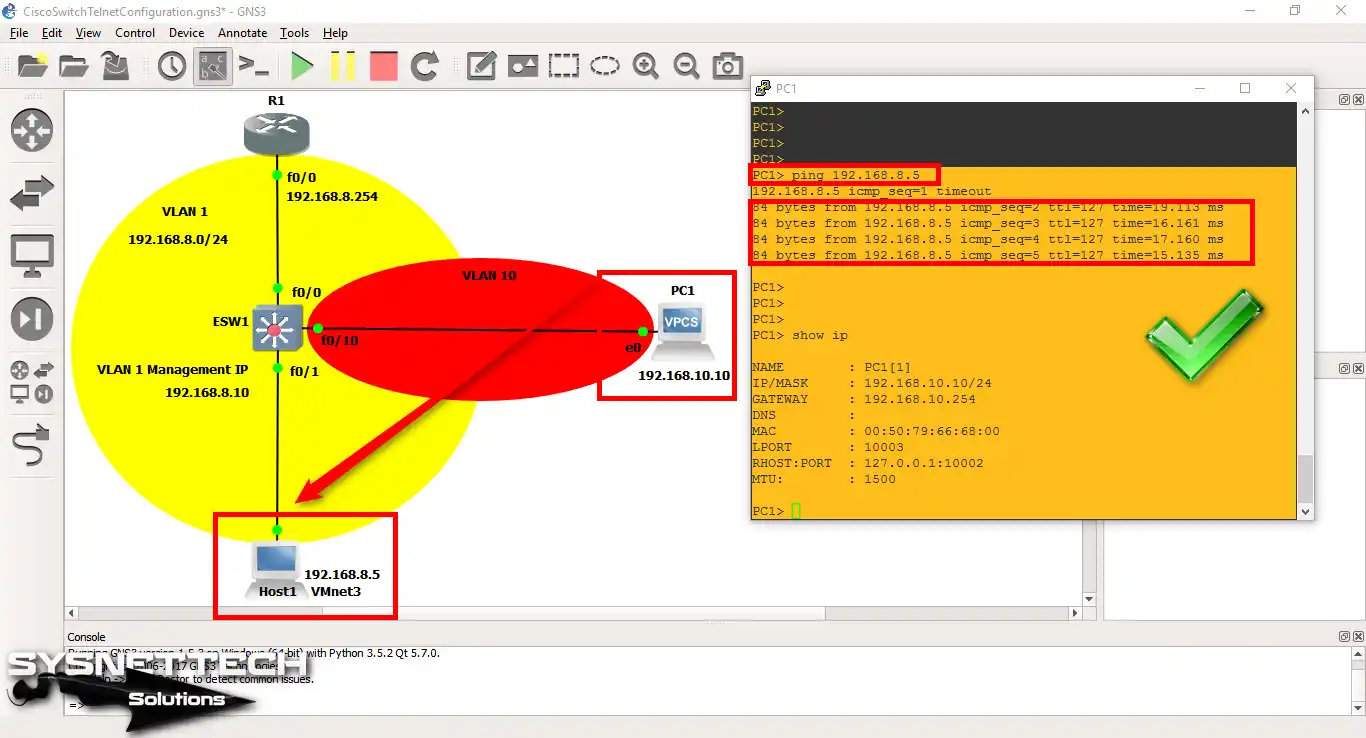
Step 5
When you ping the VMware PC via VPCS, you can observe that the process completes successfully.
Step 6
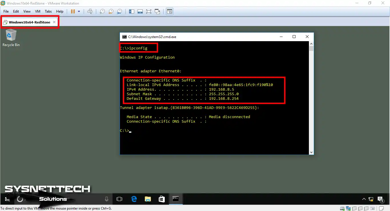
Open CMD to see your virtual machine’s TCP/IP details. Then, use the ipconfig command to check that the setup is correct for the topology.
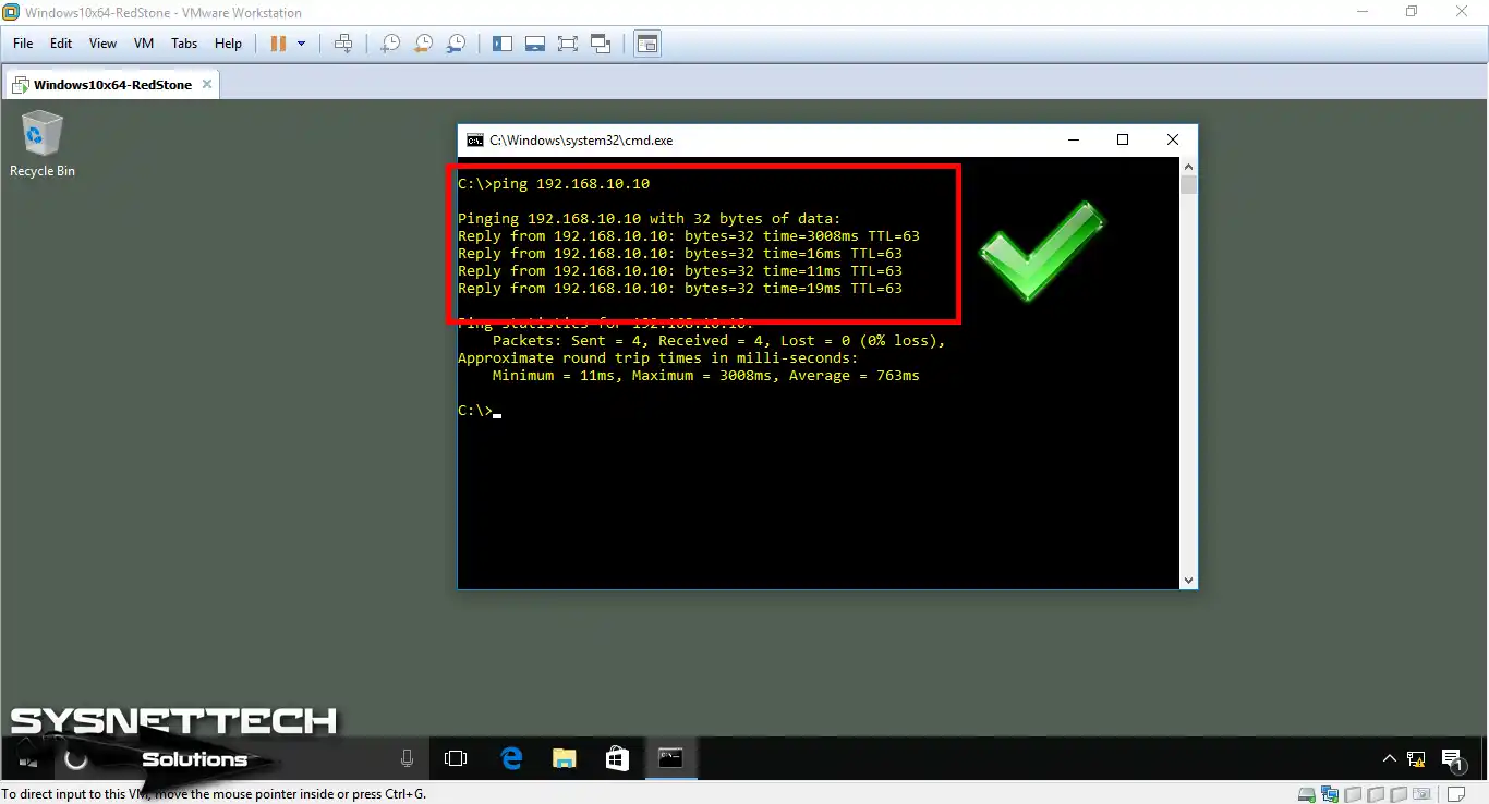
Step 7
Similarly, ping from the VM to the VPCS. At this stage, you may notice that the process is successful as desired.
Switch Basic Configuration Commands
- IT#
- IT# vlan database
- IT# conf t
- R1# conf t
- PC1>
ESW1# conf t
ESW1(config)# hostname IT
IT# conf t
IT(config)# interface fastethernet 0/0
IT(config-if)# no shutdown
IT(config-if)# exit
IT(config)# interface fastethernet 0/1
IT(config-if)# no shutdown
IT(config-if)# exit
IT(config)# username cisco password cisco123
IT(config)# line vty 0 4
IT(config-line)# login local
IT(config-line)# transport input telnet
IT(config-line)# exit
IT(config)# enable password 12345
IT(config)# enable secret 123456
IT(config)# service password-encryption
IT(config)# banner motd #
Enter TEXT message. End with the character '#'.
###Unauthorized Access###
IT(config)# ip default-gateway 192.168.8.254
IT(config)# end
IT# wr
IT# vlan database
IT(vlan)# vlan 10 name ITVLAN10
VLAN 10 added:
Name: ITVLAN10
IT(vlan)# vlan 20 name ITVLAN20
VLAN 20 added:
Name: ITVLAN10
IT(vlan)# vlan 100 name ITMANAGEMENTVLAN100
VLAN 100 added:
Name: ITMANAGEMENTVLAN100
IT(vlan)# exit
APPLY completed.
Exiting....
IT#
IT# conf t
IT(config)# interface fastethernet 0/10
IT(config-if)# switchport mode access
IT(config-if)# switchport access vlan 10
IT(config-if)# exit
IT(config)# interface fastethernet 0/0
IT(config-if)# switchport mode trunk
IT(config-if)# exit
IT(config)# end
IT# wr
R1# conf t
R1(config)# interface fastethernet 0/0
R1(config-if)# no ip address
R1(config-if)# exit
R1(config)# interface fastethernet 0/0.1
R1(config-if)# ip address 192.168.8.254 255.255.255.0
R1(config-if)# encapsulation dot1Q 1
R1(config-if)# exit
R1(config)# interface fastethernet 0/0.10
R1(config-if)# ip address 192.168.10.254 255.255.255.0
R1(config-if)# encapsulation dot1Q 10
R1(config-if)# exit
R1(config)# end
R1# wr
PC1> ip 192.168.10.10/24 192.168.10.254
Switch Configuration Commands ⇒ Video
Watch this video to learn Switch commands in the GNS3 environment. In this training, you will learn processes such as VLAN configuration and IP address assignment.
Also, I will clearly show how to control switch port management. Please remember to join our YouTube channel to see our new videos!
Frequently Asked Questions (FAQ) About Cisco Switch Initial Configuration
- Why would I want to configure a Cisco Switch using GNS3?
- What basic configurations can I perform on a Cisco Switch in GNS3?
- How can I save my Switch configuration?
- Where can I find more resources about Cisco exams with GNS3?
Conclusion
In short, setting up Cisco Switches with GNS3 is an enjoyable task. So, you can easily use physical devices while building your tech skills. Also, you get hands-on practice by getting ready for actual network problems.
By better understanding the functions of Layer 2 & 3 Cisco Switches, you can also configure VLANs. Thus, you can enhance your network performance and safer.
In short, as you discover the capabilities of GNS3, you will apply what you learn. As a result, your confidence in your networking skills will grow, and you will achieve success on your CCNA journey.
You can do simple setups and even more than that. This way, you move fast toward being a competent network engineer.
You may want to expand your knowledge about the VLAN settings I mentioned in our guide. For this reason, you can refer to our guide titled How to Configure VLAN on a Cisco L2 Switch in GNS3. In this resource, I adopted a step-by-step approach for L2 Switches. Because of this, you will be able to strengthen your network-building skills more efficiently.

Be the first to share your comment