
You can gain experience by creating simple or advanced network topologies using Packet Tracer. In addition, if you are preparing for the Cisco exams, you can perform the curriculum that the exam requires with this simulator software.
How to Create a Network in Cisco Packet Tracer
With Cisco’s free network simulator software PT, you can easily prepare for network exams. Please note that this software is not only used for one exam. At the same time, those who want to develop themselves in the field of network and system technologies are also using this program.
In Packet Tracer, you can add a Router, Switch, and PC to the working environment to create a primary network and examine how data communication takes place between computers.
This software gives you more straightforward usage by making sure you don’t have to deal with the Cisco IOS images required by GNS3. In addition, if you are an instructor, you can prepare network activities for your students and test their network knowledge.
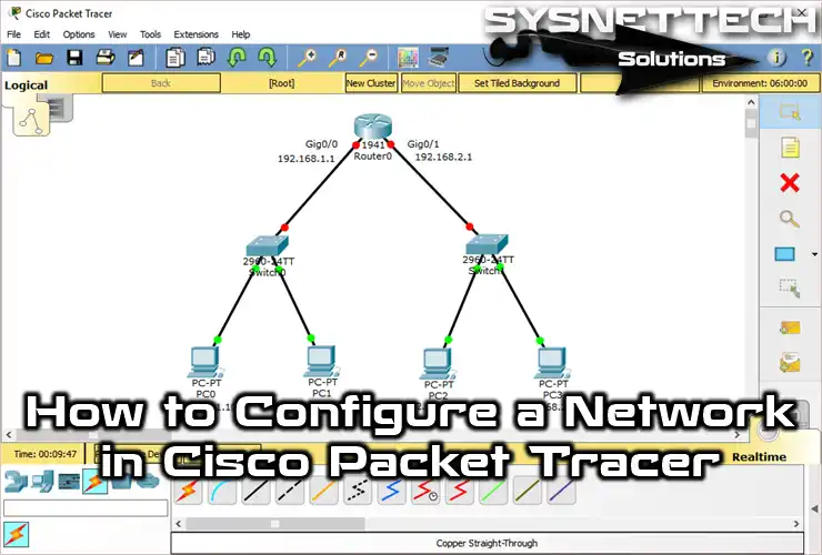
Creating a Simple LAN in Packet Tracer Topology
Now, follow the steps below to examine how computers on two segments (two different LANs) connected to the Cisco Router on Packet Tracer communicate.
Step 1
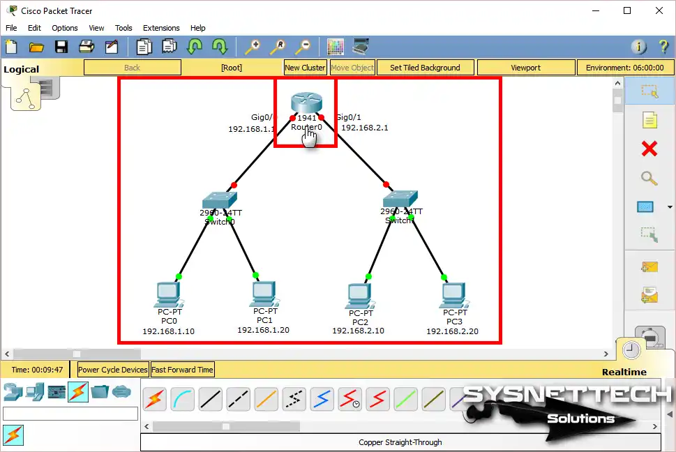
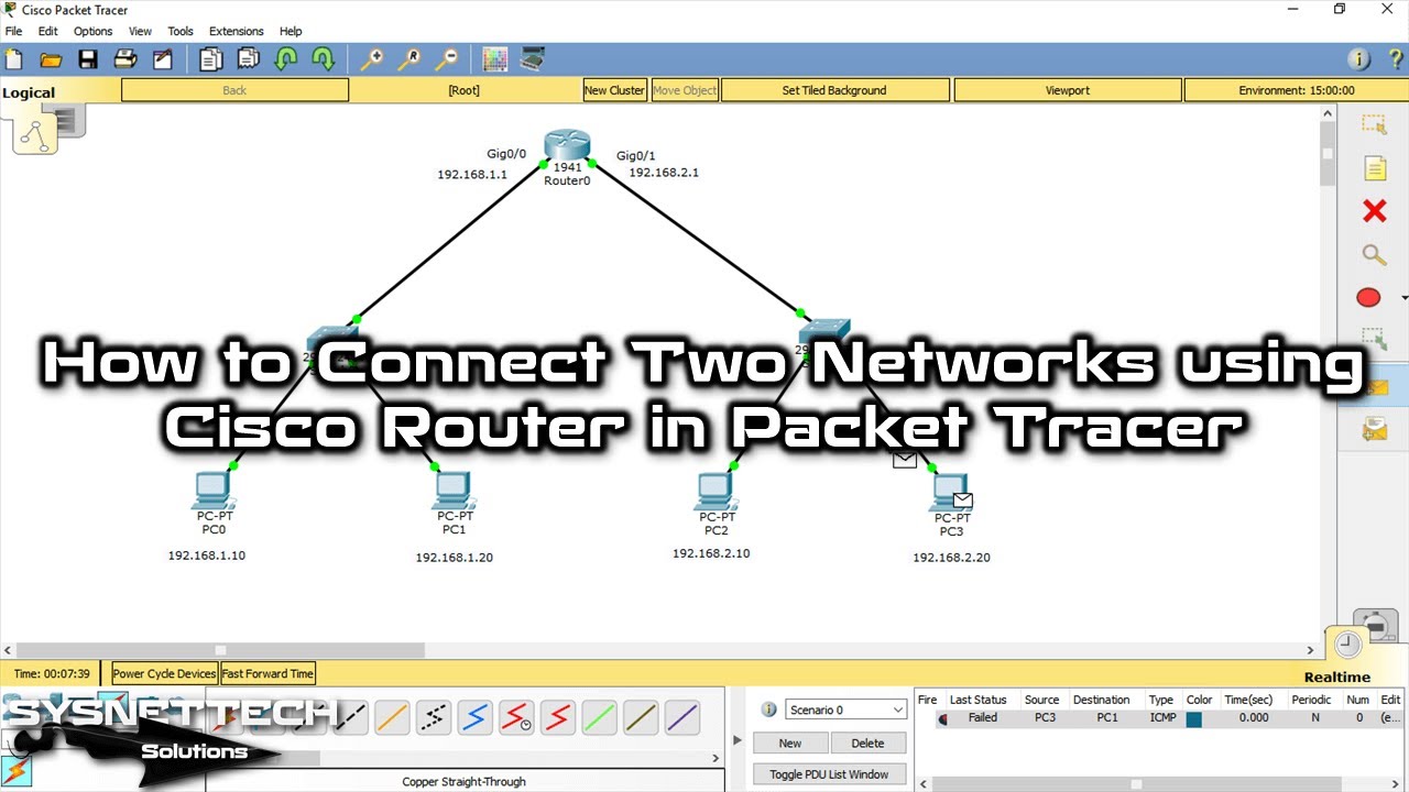
Add one Cisco Router, two Cisco Switches, and four PCs to the program’s workspace. Then, note the port and slot numbers of the Router’s GigabitEthernet interfaces in the workspace.
Double-click on the Router to open the IOS Command Interface.
Putting devices into the work area is pretty simple. But the program can do a lot more.
Here is a short summary: after you place your devices, learning how to use the work area well will help you work faster. Small things, like how you connect cables and change what you see on screen, will help you get more done.
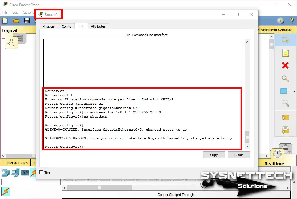
Step 2
In the Cisco router CLI window, assign an IP address to the GigabitEthernet0/0 interface and execute the no shutdown command to activate the interface.
Router>en
Router#conf t
Enter configuration commands, one per line. End with CNTL/Z.
Router(config)#interface gigabitEthernet 0/0
Router(config-if)#ip address 192.168.1.1 255.255.255.0
Router(config-if)#no shutdown
Router(config-if)#
%LINK-5-CHANGED: Interface GigabitEthernet0/0, changed state to up
%LINEPROTO-5-UPDOWN: Line protocol on Interface GigabitEthernet0/0, changed state to up
Router#
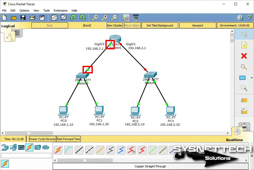
Step 3
After configuring the GigabitEthernet0/0 interface, the port will be green. The meaning of this color is that the interface is active and working.
Step 4
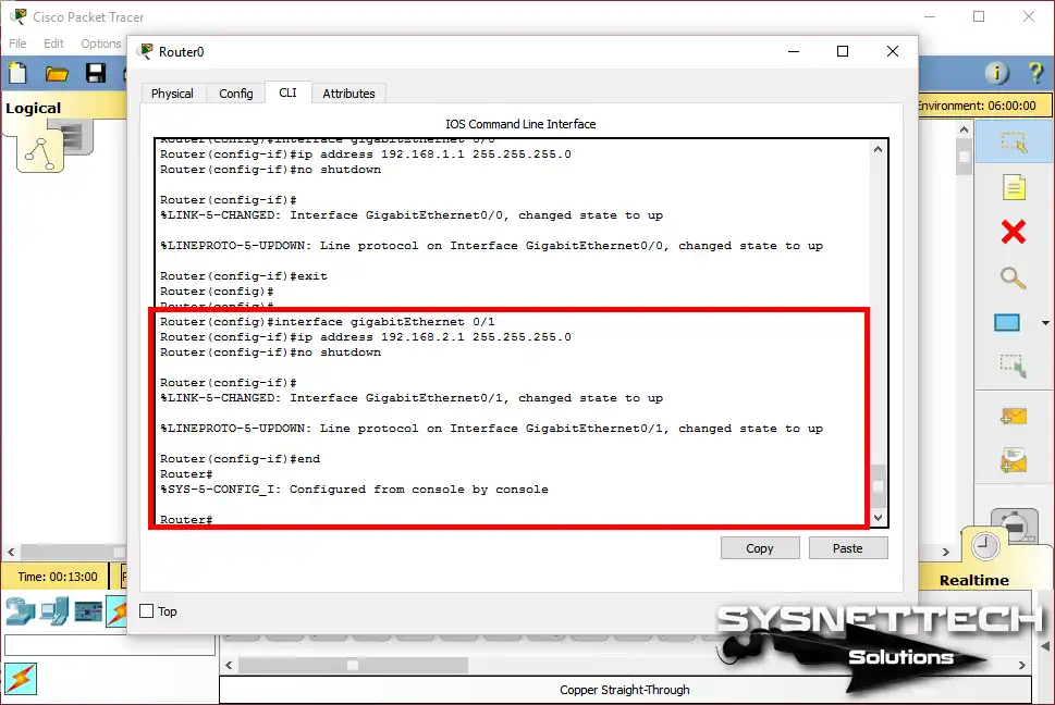
To assign an IP address to the GigabitEthernet 0/1 interface and activate the port, perform the following commands:
Router(config)#
Router(config)#interface gigabitEthernet 0/1
Router(config-if)#ip address 192.168.2.1 255.255.255.0
Router(config-if)#no shutdown
Router(config-if)#
%LINK-5-CHANGED: Interface GigabitEthernet0/1, changed state to up
%LINEPROTO-5-UPDOWN: Line protocol on Interface GigabitEthernet0/1, changed state to up
Router(config-if)#end
Router#
%SYS-5-CONFIG_I: Configured from console by console
Router#
Step 5
In the following image, you can see that the Router’s GigabitEthernet ports are connected to the Switches and are active.
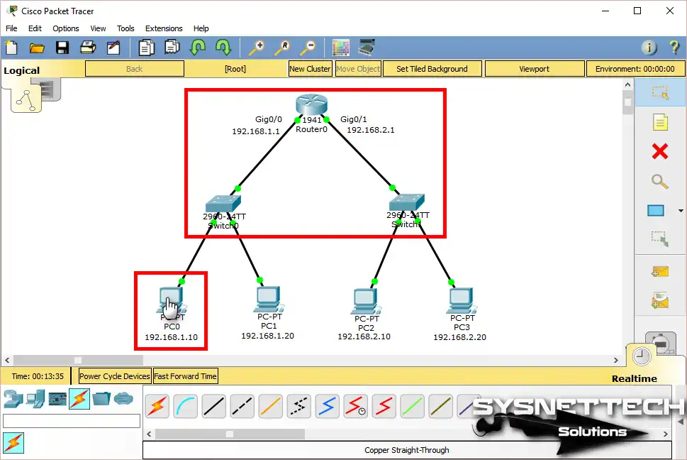
Step 6
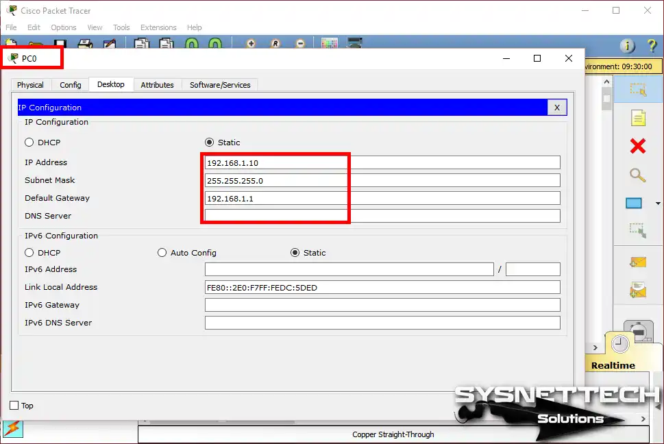
Now, you need to assign an IP address to the computers that you add to the topology. To do this, click on the PC to which you will assign an IP, and on the Desktop tab, click IP Configuration.
Then, it would be best if you addressed the PC according to the IP block of the network on which the network is. According to the topology above, assign an IP address from block 192.168.1.0/24 as PC0 is connected to the network under the Router’s Gig0/0 interface.
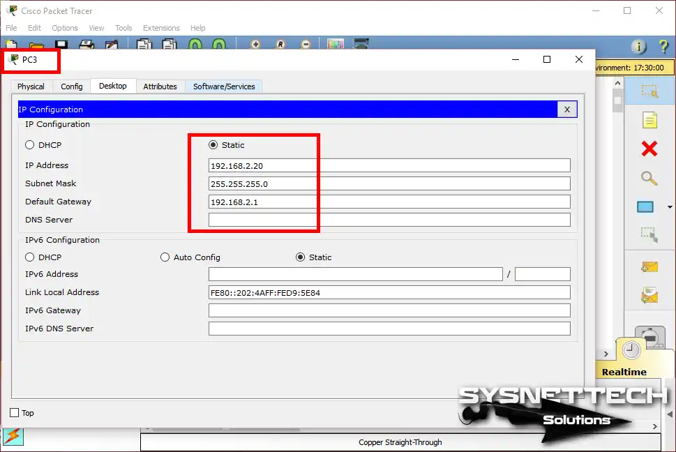
Configure the IP address, subnet mask, and default gateway settings for PC0 as in the following image.
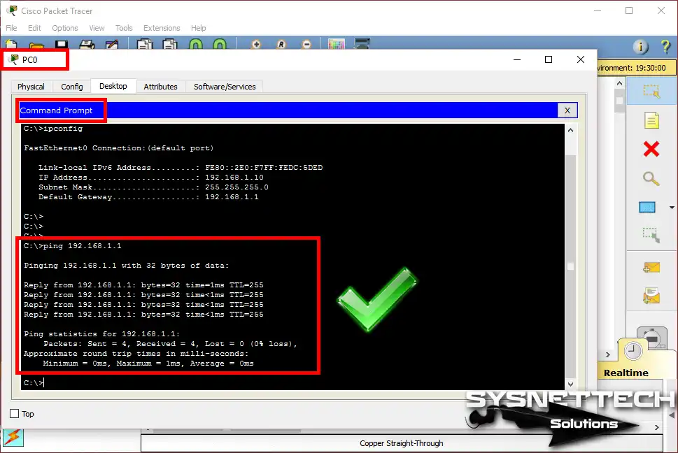
Step 7
Click Command Prompt on PC0, and then ping the Cisco Router Gig0/0 default gateway to test the network connection.
Step 8
This time, the TCP/IP settings of PC3 on the 192.168.2.0/24 network are configured as follows.
Step 9
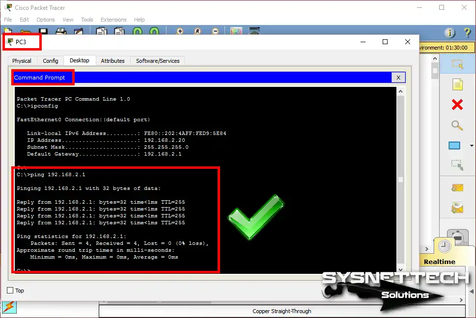
When you ping the GigabitEthernet0/1 interface (default gateway) via PC3, you can also see that the operation was successful.
Step 10
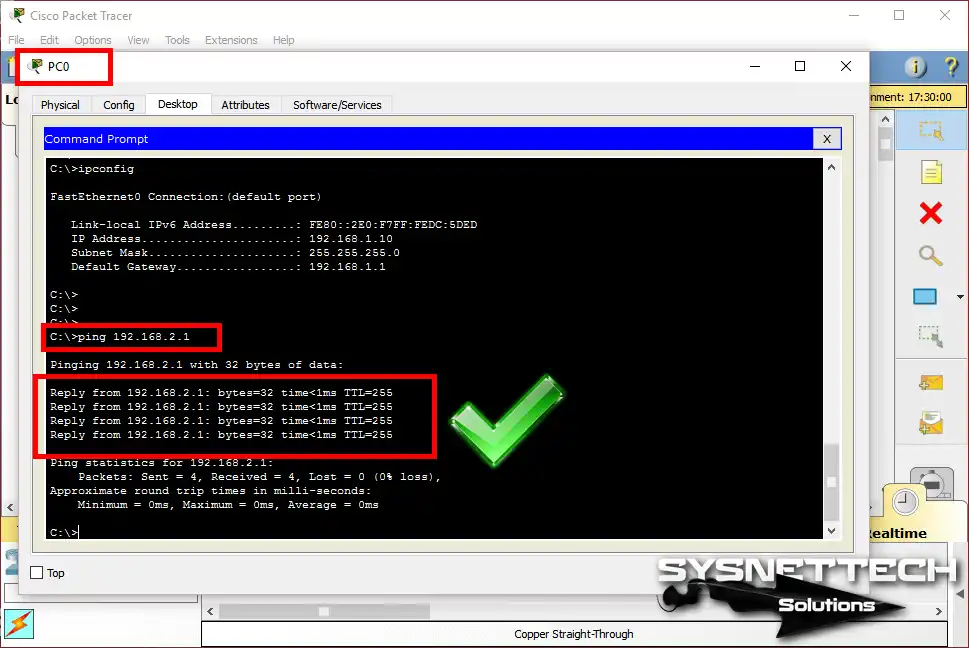
Likewise, suppose you ping the Router’s GigabitEthernet0/1 interface via PC0. In that case, the operation will still be successful because one Router’s main task is to communicate with each other the different networks connected to it.
Step 11
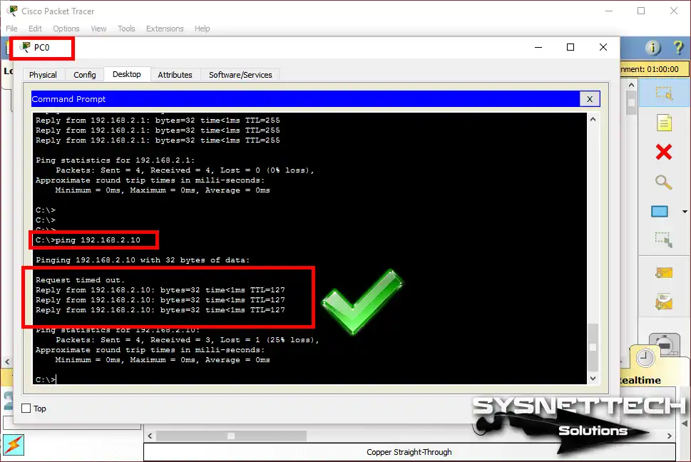
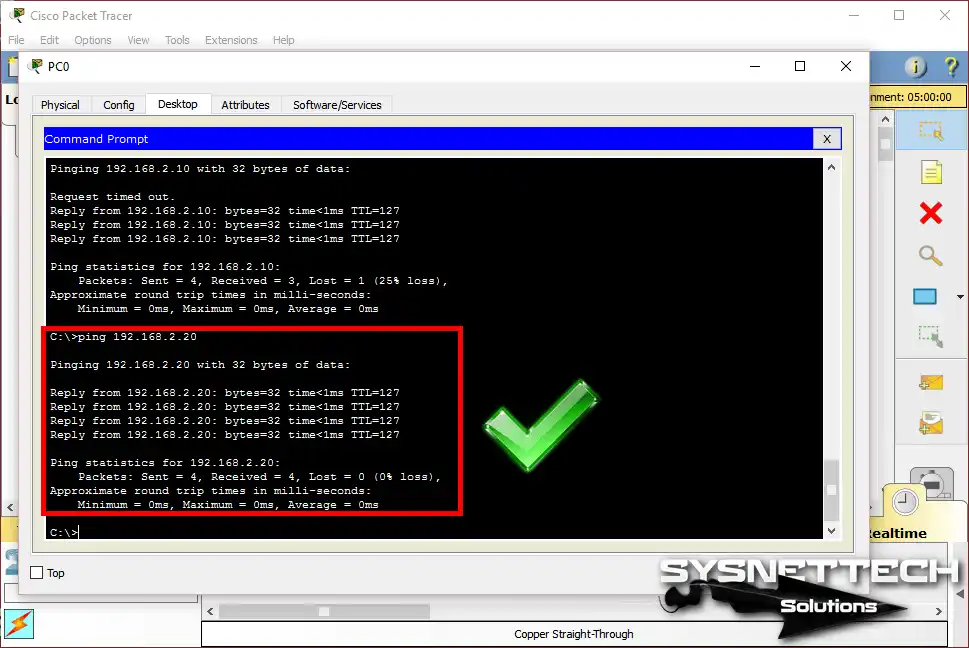
Ping operation to PC2 computer with IP address 192.168.2.10 via PC0;
Step 12
Ping operation to PC2 computer with IP address 192.168.2.20 via PC0;
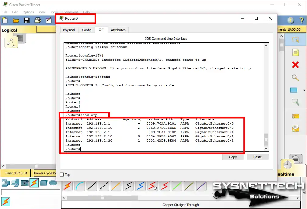
Step 13
You can examine the MAC addresses of computers when you execute the show arp command at the Cisco router CLI command prompt.
When you connect a new router, setting things by hand stops working. You need to use a dynamic protocol so routers can learn about networks far away. The idea is simple—you can try a basic RIP setup now. It feels great to see routers find each other by themselves with just a few commands.
Video
You can watch the video below to create and communicate the two networks with the Cisco simulator software. Also, subscribe to our YouTube channel to support us!
Final Word
In this article, we made a simple network on Cisco Packet Tracer. We set it up so computers in two different parts could talk to each other.
If you add another Cisco Router to the network, you must turn on a routing protocol like RIP, EIGRP, or OSPF on the Routers.
Also, choosing between GNS3 and Packet Tracer really depends on what you want to do. If you are studying for exams, the simulator is a good choice for you.
I want you to know this: learning everything the simulator can do before you start practicing will help you a lot. Knowing which protocols it works with will help you plan your study time.

Be the first to share your comment