

You face one of the most core concepts in a network engineering career. Yet people often get this concept wrong. Network segmentation, or VLAN (Virtual Local Area Network), forms the backbone of today’s cybersecurity architecture.
In a corporate network, you may want to control broadcast traffic. In fact, you must grasp this concept to close security gaps and boost performance.
We go beyond standard definitions in this post. Plus, I share rare cases and fixes from 20 years of field work. We also examine how the 802.1Q protocol works, now a must-have for modern networks. Along with that, we tackle the feared VLAN hopping attacks.
Facing current threats, knowing how to protect your network matters a great deal. So I explain sneaky attack vectors like double tagging. Also, you will find setup commands compared not just for Cisco but also for MikroTik, Huawei, and Juniper devices.
My goal is that by the end of this guide, you will have a checklist you can use right in a production setting. We blend theory with real-life use cases. We will clear up all your doubts for good. So grab your coffee and dive deep into this fascinating world of network engineering!
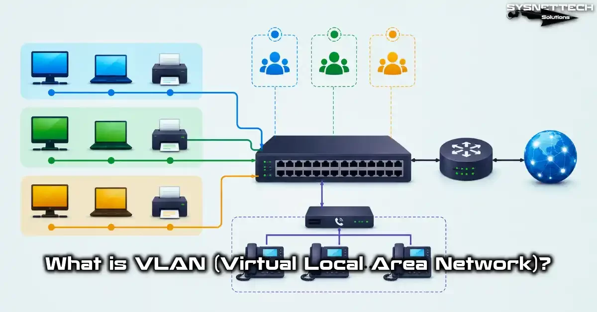
What is a VLAN? — Definition, History, and Its Place in the OSI Layer
Logical network segmentation, or VLAN, is one of the network world’s most elegant inventions. It creates a communication space that runs free of the physical layout.
To understand VLANs, first you must know the classic local area network. A LAN structure leans on physical limits. A VLAN breaks past those limits by making them virtual.
I recall the moment I set up this structure with the first Cisco 1900 series switch. I truly grasped then how creative engineering can be. Just think: you can build separate broadcast areas on one physical switch that are fully walled off from each other.
Looking back, the need for network segmentation first blew up in the early 1990s. In old flat networks, a broadcast packet from one computer reached all devices.
In the end, this caused a security flaw and badly undercut network speed. Back then, IEEE started working on the 802.1Q standard and formally released it in 1998.
VLAN technology works at the second layer of the OSI model. That is, it groups by MAC address at the data link layer. Also, a 4-byte tag added to the Ethernet frame marks which virtual network the traffic belongs to.
Plus, this happens at the hardware level, so you face almost no delay. ASIC chips run this process directly.
Advantages VLAN Technology Provides
In my experience, the biggest revolution of this tech is the flexibility it gives network admins. When you need to move a department, you no longer have to touch physical cables.
You simply change the port assignment. Then the user joins a new broadcast area at once. This freedom forms a vital base for modern corporate network topology.
What Is a Broadcast Domain? Why Does It Cause Trouble in a VLAN-Less Network?
Think of that scary scene every network engineer sees at least once in their career: a broadcast storm.
A broadcast domain covers all the nodes a network device’s broadcast frame can reach. For instance, when you send an ARP request, that request reaches every device in the same broadcast domain. So, every device there burns CPU cycles for this.
In a flat network, you do no segmenting at all. Thus, a single broadcast domain covers the whole switch. This leads to serious speed drops, mainly in networks with over 200 devices.
The ARP traffic noise grows so much that users even struggle to reach the file server. Plus, a bad actor connected to the network can easily listen to all traffic.
Sadly, many SMEs overlook this danger. I still struggle to explain that the first step to network speed tuning is broadcast domain control.
Because shrinking broadcast traffic lets you use bandwidth in a smart way and narrows the attack surface. Also, it makes finding issues much easier from a network management view.
The table below clearly shows the gap between networks that use VLANs and those that don’t:
| Feature | Flat Network Without VLANs | Segmented Network With VLANs |
|---|---|---|
| Number of Broadcast Domains | 1 (all devices same domain) | Separate domain for each VLAN |
| Security Isolation | None (everyone sees everything) | Yes (isolation between VLANs) |
| Performance Impact | High CPU use, slowdown | Low CPU use, stable |
| Ease of Troubleshooting | Hard (all traffic mixed) | Easy (isolated segments) |
| Scalability | Very low | Very high |
IEEE 802.1Q Standard: The 4-Byte VLAN Tag Structure
Think of a standard Ethernet frame. After the source and target MAC addresses, the EtherType field normally comes next.
The 802.1Q protocol steps in right at this point. It adds a 4-byte tag to the frame. It uses 0x8100 as the Tag Protocol Identifier (TPID). Frankly, this value shows the frame is tagged.
When you look inside the tag, you see a 3-bit Priority Code Point (PCP) for QoS priority setting.
After that comes a 1-bit Drop Eligible Indicator (DEI). It marks that you can drop the frame during congestion. Finally, you find the 12-bit VLAN ID (VID) field. This field can take a value from 0 to 4095.
But there is a key detail you must note. The standard reserves VID 0 and 4095. The remaining 4094 usable IDs were enough for many years even for large data centers.
However, in modern cloud setups, the 4096 VLAN limit and its fixes are now a serious topic of debate. That’s precisely why overlay tech like VXLAN was born.
The table below details the 4-byte structure of the 802.1Q tag:
| Field Name | Length | Explanation | Example Value |
|---|---|---|---|
| TPID | 16 bit (2 bytes) | Tag protocol identifier | 0x8100 |
| PCP | 3 bit | QoS priority level (0-7) | 5 (voice traffic) |
| DEI | 1 bit | Drop eligibility indicator | 0 or 1 |
| VID | 12 bit | VLAN ID number (1-4094) | 100 |
VLAN vs Subnet: Why Use Both Together?
This question has confused students since the very first CCNA classes. A subnet is an IP addressing and network-splitting method that works at the third OSI layer.
Meanwhile, a VLAN splits broadcast domains at the second layer. The two are not rivals; they complement each other. You cannot choose one over the other.
With CIDR addressing in IP planning, you split subnets well. When you use VLAN and CIDR together, the structure becomes very flexible.
In practice, we always use a one-to-one mapping. That is, one VLAN ID matches one IP subnet. For instance, we assign the 192.168.10.0/24 subnet to VLAN 10, and the 192.168.20.0/24 subnet to VLAN 20.
This way, we get isolation at the second layer and routing at the third layer. Also, writing firewall rules by subnet is much easier.
Real-World Impact and Comparison
Years ago, I knew a manager at a production site. Because he couldn’t grasp this logic, he tried to run all VLANs on the same IP block.
The result was a total mess. Devices could not get IPs, DHCP clashes happened, and the network kept crashing. After that day, I started stressing the importance of network isolation and IP planning at every chance.
Here is a full comparison table summing up the key differences between the two:
| Feature | VLAN (Layer-2) | Subnet (Layer-3) |
|---|---|---|
| Working Layer | OSI Layer 2 (Data Link) | OSI Layer 3 (Network) |
| Identification Method | 802.1Q tag (VLAN ID) | IP address and subnet mask |
| Isolation Type | Broadcast domain isolation | IP-level isolation |
| What’s Needed for Communication | Inter-VLAN routing (L3 device) | Router or L3 switch |
| Flexibility | Free from physical location | Depends on IP plan |
| Best Use | Together (one-to-one mapping) | Together (one-to-one mapping) |
Access Port and Trunk Port: The Cornerstones of VLAN Setup
In the switch world, ports are like the gates of a castle. Each gate has a set purpose and access level.
An access port carries untagged traffic for just one virtual network. End-user computers, printers, or IP cameras usually plug into these ports. The device in question never knows it is inside a network segment.
On the other hand, the trunk port feature is a whole different beast. Developers designed this port for a special task. Plus, it carries traffic from many virtual networks over one physical link.
Every frame moving over a trunk link gets marked with an 802.1Q tag. That way, the switch on the other side spots at once which broadcast domain the incoming packet belongs to.
In the kitchen of the job, one of the most common mistakes I see is mixing up the access and trunk port ideas. If you wrongly set a switch port as trunk, the end device cannot read the tagged frames. As a result, the connection breaks.
To stop these errors, you must always clearly define the port type. Also, you should use auto protocols like DTP in a controlled way.
The table below clears up the key differences between the two port types.
| Feature | Access Port | Trunk Port |
|---|---|---|
| Number of VLANs Carried | 1 (Data VLAN) | Multiple (All allowed VLANs) |
| Tagging | Untagged | Tagged – except Native |
| Purpose of Use | End-user devices | Switch-to-switch or switch-to-router link |
| Default State | Dynamic Auto (some models) | Dynamic Desirable (some models) |
| Security Risk | Low (with correct setup) | High (VLAN hopping risk) |
Access Port Setup (Cisco, MikroTik, Huawei, Juniper)
I’m sharing the setup steps I use most in the field. In the Cisco world, to put a port in access mode, you first give the switchport mode access command.
Then, you say switchport access vlan 10 to assign the port to the network you want. You may see this as very simple. Yet behind the scenes, a huge MAC-address-based grouping machine runs.
On the MikroTik side, things move a bit differently. You need to turn on the Bridge VLAN filtering feature and set the PVID value for each port.
With the /interface bridge vlan add bridge=bridge1 vlan-ids=10 tagged=ether1 untagged=ether2 command, you assign ether2 to VLAN 10 as untagged. RouterOS’s flexible build offers a quick setup edge, mainly in small networks.
On Huawei and Juniper gear, the logic is the same. On Huawei, you use the port link-type access and port default vlan 10 commands.
On Juniper, the set interfaces ge-0/0/0 unit 0 family ethernet-switching vlan members vlan10 structure rules. You see, the basic rule never changes, even as the vendor shifts. They all lean on the same IEEE standard.
show lldp neighbors command, in particular, gives you great visibility by listing the neighbor devices on the network.The step-by-step path for access port setup goes like this:
- Pick the port:
interface GigabitEthernet0/1 - Set port mode to access:
switchport mode access - Assign the VLAN ID:
switchport access vlan 10 - Turn off DTP:
switchport nonegotiate - Activate the port:
no shutdown - Verify:
show vlan briefandshow interfaces switchport
Trunk Port Setup and the Allowed VLAN List
A trunk port setup is as critical as your firewall rules. On Cisco, you start with the switchport mode trunk command. However, you must never stop there.
By default, all VLANs pass through a trunk. Yet best practices say you should carry only the IDs you need. So, right after that, you must give the switchport trunk allowed vlan 10,20,30 command.
On MikroTik, you reach the same result by making a tagged port list. The /interface bridge vlan add bridge=bridge1 vlan-ids=10,20,30 tagged=ether1 command makes ether1 act as a trunk only for the stated IDs. Plus, this method lets you build custom permit lists for each port.
I want to share a habit I picked up over the years. Every time I set up a new trunk link, I always check with the show interfaces trunk command.
Because one ID left out by mistake in the allowed list can cause hours of troubleshooting sessions. Also, removing needless broadcast domains from the trunk cuts ARP traffic noise and broadcast storm risk.
Apply the trunk setup steps in order:
- Pick the port:
interface GigabitEthernet0/24 - Turn on trunk mode:
switchport mode trunk - Set the encapsulation protocol:
switchport trunk encapsulation dot1q - Limit allowed VLANs:
switchport trunk allowed vlan 10,20,30,100 - Change the Native VLAN:
switchport trunk native vlan 999 - Verify:
show interfaces trunk
Why You Must Change the Native VLAN (Security Gap Detail)
This topic has turned into a personal security obsession for me. The Native VLAN is the network where frames travel untagged over a trunk port. By default, this ID is 1.
At this point, you face a serious security hole. Because attackers exploit this default setup with methods like double tagging.
In the past, during a pen test I ran at a financial firm, I saw that the Native VLAN still sat at 1. Using this weakness, an attacker slipping into a different broadcast domain was no big feat.
So, changing this default ID is not just a tip; it’s a must-do security step. For a new value, you should pick a random unused ID (for example, VLAN 999).
The change process is extremely simple. On Cisco, applying the switchport trunk native vlan 999 command is enough.
However, never forget to make this change on both ends of the trunk. Or you will get a native VLAN mismatch error. On top of that, CDP will flood your console with warning notes. These warnings are the sign of a wrong setup.
VLAN Hopping Attacks: Switch Spoofing and Double Tagging (Real-World Attack Analysis)
We will talk about one of the oldest yet still most effective layer-2 attacks in the security world.
VLAN hopping is an action cyber attackers take. Frankly, the attacker leaves their own broadcast domain and slips into another virtual network.
I first watched this attack live at a security conference in 2002. Truly, that moment fully changed my view on network security.
There are two main VLAN hopping methods. The first is switch spoofing, where the attacker presents themselves as a switch and sets up a trunk link.
We know the second as the double tagging attack. Plus, this method uses the Native VLAN weakness. Both methods work incredibly well on poorly set up switches.
For instance, I audited a large hospital network in 2018. Frankly, I saw that an attacker had reached the patient record system using this method.
The attack happened exactly because the auto trunk negotiation feature was left on. After that day, I made turning off DTP on all client ports a standard process. Now let’s detail these attack vectors.
Switch Spoofing Attack: How a Trunk Gets Seized via DTP
Dynamic Trunking Protocol is a Cisco protocol that lets switches auto-set trunk links. Yet this ease brings a huge security gap with it.
With special software on their computer, the attacker acts like a switch and sends DTP packets. The moment the other switch gets these packets, it turns the port into trunk mode on its own.
In other words, the attacker can now see all tagged traffic. Even worse, they can tag their own frames and inject them into any broadcast domain they want.
The scariest side of this attack is that it happens fully in silence and leaves no trace. Because the switch logs only show that a trunk link was set up.
Or rather, stopping this attack is extremely simple. On all client ports, you must turn off DTP using the switchport mode access and switchport nonegotiate commands.
Plus, you need to shut down all unused ports and assign them to a black hole VLAN. Because even an empty wall Ethernet jack is a potential entry point for an attacker.
switchport nonegotiate command. The two together give full protection.Double Tagging Attack: Exploiting the Native VLAN Weakness
This attack is a bit more complex but just as clever. To reach the victim’s virtual network, the attacker uses a double-layered 802.1Q tag.
The first tag belongs to the attacker’s own broadcast domain. The second tag carries the target network’s ID. When the attacker sends the frame, the first switch sees the first tag and forwards it within its own network.
However, the second switch’s trunk port strips off the first tag because it carries the Native VLAN untagged. Then, it reads the second tag and sends the frame to the target network.
This frame, which looks like it never left the attacker’s own broadcast domain, is now inside the victim’s network. Since there is no return traffic, the attack is one-way but still very dangerous.
To block this attack, you must change the Native VLAN to an unused ID. What’s more, you must force tagged transport on all trunks.
The vlan dot1q tag native command provides this protection. Even some modern switches have started turning this feature on by default. Luckily, the sector is moving in the right direction on this.
Checklist to Protect Against VLAN Hopping (For All Vendors)
By applying the steps below in order, you can protect your network from VLAN hopping attacks:
- Set all client ports to access mode and turn off DTP (
switchport mode access,switchport nonegotiate). - Change the Native VLAN from the default 1 to a different, unused ID. Also, update this change on both ends of the trunk.
- Shut down all unused ports (
shutdown) and assign them to a Black Hole VLAN. - On trunk ports, limit the allowed VLAN list to only the IDs you need.
- If possible, also tag native traffic with the
vlan dot1q tag nativecommand. - On all switches, set VTP to transparent mode or turn it off fully.
- Turn on the Port Security feature on all access ports.
- Regularly check the
show interfaces trunkoutputs.
VLAN Types in Depth: Data, Voice, Management, Native, Private, Black Hole VLAN
As a network architect, you know each virtual network has a set task and character. The Data VLAN, as the name says, carries user data traffic.
We usually create a separate data ID for each department. For instance, VLAN 10 for accounting, VLAN 20 for marketing. This way, a broadcast storm in one department does not hit the other.
The Voice VLAN is a whole different world. Developers designed this network specifically to carry VoIP phone voice packets.
In this type, QoS setup is vital. Because voice packets are extremely sensitive to delay. The phone learns its own voice network on its own via LLDP or CDP. Along with that, it sends all voice traffic tagged.
The Management VLAN is a special admin network that lets network managers reach switches and routers from afar. This network must be fully isolated from user traffic.
In particular, you should allow access to the management interface only from specific IP addresses. Also, protocols like SNMP and SSH must work only over this network.
The table below sums up the most common VLAN types and their purposes:
| VLAN Type | Typical VLAN ID | Purpose | QoS Requirement |
|---|---|---|---|
| Data VLAN | 10, 20, 30… | User data traffic | Low-Medium |
| Voice VLAN | 100, 200… | VoIP phone traffic | High (DSCP EF) |
| Management VLAN | 99, 999… | Device management | Medium |
| Native VLAN | 999 (changed) | Trunk untagged traffic | Low |
| Black Hole VLAN | 666, 999… | Unused ports | None |
Private VLAN (PVLAN): Primary – Secondary (Isolated/Community)
Private VLAN is an advanced feature that restricts devices inside the same broadcast domain from talking to each other.
The primary ID handles contact with the outside world. Meanwhile, the secondary IDs hold isolated or community ports. This setup is incredibly useful, mainly in a DMZ zone or multi-tenant data centers.
For example, think of a web server farm. All servers must be on the same network but should not talk to each other directly. That’s where isolated ports step in.
These ports can only contact the outside world through the promiscuous port. Community ports can talk among themselves but cannot reach other communities. It is tailor-made, mainly for scalable network architecture.
However, PVLAN setup can be complex. The promiscuous port is the only point that can talk with all secondary ports. Setting this port wrong breaks all isolation.
So, when building a PVLAN, you must always check twice and verify with test cases. Private VLAN port isolation, when applied right, is a perfect layer for network security policy.
| PVLAN Port Type | Can Talk To | Cannot Talk To | Use Case |
|---|---|---|---|
| Promiscuous | Everyone (all secondary ports) | – | Router, firewall connection |
| Isolated | Only promiscuous port | All other ports | DMZ servers, guest users |
| Community | Promiscuous + same community members | Other community and isolated ports | Same project team servers |
Black Hole VLAN (Sinkhole VLAN): Blacking Out Traffic During Security Events
As the name suggests, a Black Hole VLAN is a virtual black hole. That is, traffic that enters never leaves again.
By assigning all unused switch ports to this network, you block potential attackers from slipping into the network. Someone who plugs a cable into a wall jack and tries to get an IP finds themselves in a fully isolated setting.
Along with that, this network has a much more sophisticated use. When you spot a security breach, you can throw the suspect device into this black hole right away.
The device loses all network connection while you keep doing remote forensic analysis. Plus, the attacker does not spot this isolation right away.
Its setup is extremely simple. Assigning all unused ports to this special network with a command like switchport access vlan 999 is enough.
The key point is to assign no Layer-3 interface (SVI) to this ID. That is, this network must have no exit anywhere. Also, you must remove this ID from the allowed list on trunk ports.
Voice VLAN and QoS: Giving Priority to VoIP Traffic
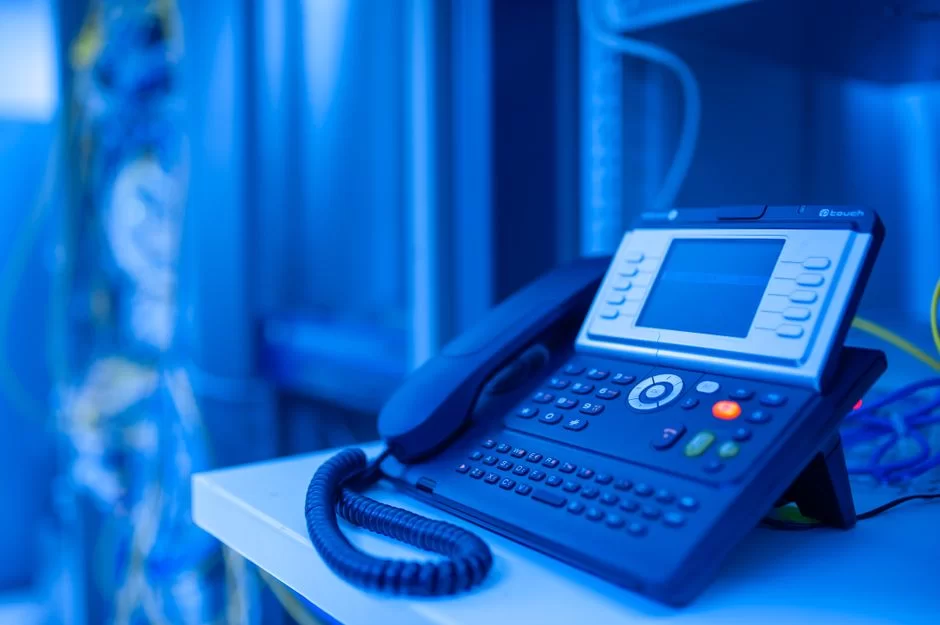
In today’s offices, desktop phones are nearly as common as computers. These devices often act as a bridge between the computer and the wall jack.
The phone’s built-in switch passes computer traffic untagged while sending its own voice packets tagged. Thanks to this tagging, the system carries voice traffic on a separate virtual network.
Yet just separating them is not enough. Voice packets race against milliseconds. So, QoS setup is a must. On Cisco, the auto qos voip trust command automates this setup to a large extent.
By reading the DSCP values the phone marks, the switch places voice packets into the priority queue. As a result, even when the network is busy, voice quality stays clear.
Still, manually setting up Voice VLAN QoS gives you more precise control. The LLDP-MED protocol lets the phone learn which network it belongs to on its own.
Plus, it also decides which QoS policy to apply this way. Thus, you do not have to set up each new phone one by one when plugged in.
mls qos trust dscp command to make the switch trust the DSCP values.Management VLAN: Best Practices for Out-of-Band Management
The management network is the brain of your network infrastructure. Access to this network must be kept apart from user traffic. By the out-of-band principle, you carry management traffic over a dedicated path.
In other words, you use a physical or logical line for this task. This way, users’ heavy data traffic does not affect management access.
Among the best practices, you allow access to the management interface only from a specific IP range. You can apply an access control list to VTY lines with the access-class command.
Also, you use SSH instead of Telnet for management. On top of that, you set a read-only string in SNMP. As a result, you must shut down needless services.
Personally, I tie the management interface on all my devices to a separate loopback address. This creates a management point that is always reachable, free from the device’s physical ports.
Plus, with this method you do not depend on trunk links for management access. Naturally, this also adds more layers to network security.
The golden rules for Management VLAN are as follows:
- Never leave the management network on VLAN 1. Always move it to a dedicated VLAN ID.
- Always use SSH v3 for management access. Also, turn off Telnet and HTTP.
- Change SNMP community strings from the default “public”/”private” values.
- Allow access to the management network only from authorized IP addresses.
- Audit all management sessions with AAA (Authentication, Authorization, Accounting).
Inter-VLAN Routing: How to Establish Communication Between VLANs
Devices in different virtual networks cannot talk to each other by default. In fact, the core goal of network isolation strategy is this.
However, what will you do when the accounting server needs to reach a printer in the marketing department?
Right at this point, Inter-VLAN routing steps in. This is the process of routing traffic between different broadcast domains using a Layer-3 device.
In the past, we had to use an external router for this task. The router on a stick method was the backbone of data centers for years.
Today though, Layer 3 switches route at hardware speed. They take on this task in a much more efficient way. The use of Switch Virtual Interface (SVI) has become the standard architecture of modern networks.
Yet traffic control does not end here. To keep Layer-2 isolation going at Layer-3 too, you must use ACL or Zone-Based Firewall.
Just because you can route does not mean you can allow all traffic. On the contrary, this would undermine your network segmentation strategy. So, you must always act with the least privilege rule. The table below compares the two main routing methods.
| Feature | Router-on-a-Stick | Layer 3 Switch (SVI) |
|---|---|---|
| Routing Speed | Software-based, limited | Hardware-based (ASIC), high |
| Port Usage | One physical port is enough | Needs an SVI for each VLAN |
| Scalability | Low (bandwidth sharing) | High (wire-speed routing) |
| Cost | Low | Medium-High |
| Redundancy | Single point of failure risk | Can be backed up with HSRP/VRRP |
Router-on-a-Stick Method: VLAN Routing with Sub-Interface
This classic method splits a single physical router interface into multiple logical sub-interfaces. Each sub-interface acts as the gateway for a specific virtual network.
For instance, with the interface GigabitEthernet0/0.10 command you create a sub-interface for VLAN 10. Then, with the encapsulation dot1Q 10 command, you match this sub-interface to the related ID.
The biggest edge of this method is cost. With one router port and a trunk link, you can route between dozens of networks.
In fact, I still use this method in lab settings to quickly set up test cases. Yet all traffic passes over one physical link. So, you hit a bottleneck in places that need high bandwidth.
The most common mistake during Router-on-a-Stick setup is forgetting the Native VLAN. On sub-interfaces, you must use the encapsulation dot1Q 10 native command for the native ID.
Also, you must make sure the same native ID is defined on both ends of the trunk on the router side. Otherwise, routing fails and you spend hours troubleshooting.
no shutdown. Also, make sure you state the correct VLAN ID in the encapsulation command for each sub-interface.Layer 3 Switch and SVI (Switch Virtual Interface)
The heart of modern corporate networks is Layer 3 switches. These devices can do both Layer-2 switching and Layer-3 routing.
Did you know switches have different switching types? Modes like cut-through and store-and-forward affect speed. In fact, this detail plays a role in how VLAN traffic gets processed.
A Switch Virtual Interface SVI is a logical Layer-3 interface you create for each virtual network. You build this interface with the interface vlan 10 command, assign an IP address, and use it as the gateway.
Layer 3 switch routing happens at hardware speed thanks to ASIC chips. This offers much higher speed compared to the Router-on-a-Stick method.
Also, you do not need an external device for the routing job. For all these reasons, I always suggest using Layer 3 switches in new installs.
To combine multiple physical links into one logical link, EtherChannel is ideal. This way, you boost bandwidth and get redundancy.
Of course, every good thing has a price. Layer 3 switches cost more and their setup is more complex. You must not forget the ip routing command to turn on IP routing.
Plus, creating an SVI for each VLAN requires a very careful IP addressing plan. Still, the speed and flexibility it provides are well worth the effort.
Follow the SVI setup steps in order:
- Turn on global IP routing:
ip routing - Create the SVI:
interface vlan 10 - Assign an IP address:
ip address 192.168.10.1 255.255.255.0 - Activate the interface:
no shutdown - Add DHCP relay if needed:
ip helper-address 192.168.100.10 - Verify:
show ip interface briefandshow ip route
Traffic Control Between VLANs: ACL and Zone-Based Firewall
Allowing everything just because routing works is like a house with no firewall. Access Control List (ACL) is the most basic tool for traffic control. Standard ACLs look only at the source IP.
Extended ACLs filter by source, destination, protocol, and port number. For instance, you allow only the accounting server to reach a specific port.
Zone-Based Firewall is a more sophisticated approach. You split your network into security zones and define traffic policies between zones.
This method greatly simplifies ACL management, mainly in multi-segment corporate networks. Also, it uses stateful inspection, allowing return traffic on its own.
My personal choice always leans on the least privilege rule. I first close all traffic, then allow only what is needed.
This approach gives you a bit of trouble at the start. Yet in the long run, it brings great ease in terms of security and manageability. You can only apply network security policy in an effective way like this.
| Feature | Standard ACL | Extended ACL | Zone-Based Firewall |
|---|---|---|---|
| Filtering Criterion | Source IP only | Source, destination, port, protocol | Zone-based stateful inspection |
| State Info | Stateless | Stateless | Stateful |
| Setup Complexity | Low | Medium | High |
| Best Use | Simple allow/deny | Detailed traffic control | Multi-segment corporate network |
DHCP Relay: Distributing IPs to All VLANs with a Single DHCP Server
Setting up a separate DHCP server for each network is costly. Plus, this method is a tough fix to manage. Yet by using a DHCP relay agent, you can hand out IPs to all virtual networks from a single central server.
This feature is vital, mainly in medium and large networks. Because it centralizes IP management and cuts operational load.
Its working logic is quite simple. When a client sends a DHCP request, this request stays inside its own broadcast area because it is a broadcast packet.
The DHCP relay agent turns this broadcast into a unicast packet and sends it straight to the DHCP server. It also relays the server’s reply back to the client. This way, devices in different networks can get IPs without trouble.
One of the most common mistakes I see in the field is forgetting the DHCP relay setup. You create a new network but clients cannot get IPs.
You check the switch setup for hours, then finally spot this missing piece. So, I never forget to add DHCP relay to the checklist when setting up a new network.
DHCP Relay Setup on Cisco Switch (ip helper-address)
In the Cisco world, we use the ip helper-address command for DHCP relay setup. You apply this command to the SVI interface of the client network.
For instance, you go under interface vlan 10 and type ip helper-address 192.168.1.10 to point to the DHCP server’s IP address. That’s all it takes.
However, there is one point you need to note. IP helper-address forwards not just DHCP packets but also other UDP broadcasts (like TFTP, DNS). This can create a security risk.
Luckily, you can control this behavior with the no ip forward-protocol udp command. If you want only DHCP packets to pass, you must turn off the other protocols one by one.
But the DHCP server may sit on a different network. In that case, you must also define the related scopes on the server side. You should set the correct IP pool for each network. Besides that, you must also enter the default gateway info.
Also, you must make sure firewall rules allow DHCP traffic. When these three parts work together, the system runs without trouble. Thus, even if you do network segmentation, you easily handle IP distribution.
DHCP Relay with MikroTik and pfSense

MikroTik RouterOS offers the DHCP relay function in an extremely flexible way. Under the /ip dhcp-relay menu, you turn on the relay agent and set which interfaces it listens on.
With the add name=relay1 interface=bridge1 dhcp-server=192.168.1.10 command, you can forward requests coming through bridge1 to the stated server. Also, you can set the source address of the relay traffic with the local-address parameter.
pfSense is the star of the open-source world. To turn on the DHCP Relay service, you go to Services > DHCP Relay menu. Here, you define the interfaces to listen on and the IP of the target DHCP server.
pfSense’s biggest edge is that it can also work as a firewall and VPN server at the same time. Thus, in small offices, you meet many needs with a single device.
You can run into a common mistake on both platforms. The relay agent uses its own interface IP as the source IP when sending the request to the DHCP server. You must make sure this IP is known on the server side.
Also, the device with the relay agent must have the right routes defined toward the client networks. Otherwise, the reply from the server cannot reach the client.
| Feature | Cisco IOS | MikroTik RouterOS | pfSense |
|---|---|---|---|
| Setup Command | ip helper-address | /ip dhcp-relay add | Web GUI > DHCP Relay |
| Listening Interface | SVI (interface vlan) | Bridge or VLAN interface | VLAN interface |
| Extra Features | UDP broadcast filtering | local-address setting | Built-in firewall |
| Difficulty Level | Medium | Medium | Low (GUI-based) |
VTP (VLAN Trunking Protocol) and Security Risks: Should You Use It or Turn It Off?
The VTP feature is a special protocol Cisco developed to auto-distribute the virtual network database. This protocol ends the hassle of setting up hundreds of devices one by one in a big network.
Plus, it promises to update all switches from a central server. Sounds great, right? Yet my field experience shows this protocol brought nothing but headaches.
In the past, a colleague of mine wrongly plugged in a switch with a higher revision number. The result was the wipeout of the whole production network setup.
That’s why you must always be careful with VTP domain setup. Or rather, if possible, you should turn it off fully or run it in transparent mode.
VTP version 3 fixed some of these issues but still does not remove the risks fully.
Experts do not suggest VLAN Trunking Protocol (VTP) in modern network design due to security risks. Instead, doing manual setup on each switch has now become the standard practice.
If you need automation, you can do controlled distribution using Ansible or Python scripts. This way, you get both the edge of central management and escape the risks VTP brings.
VTP Modes: Server, Client, Transparent
VTP has three operating modes. Server mode lets you make setup changes and spread them to other switches.
Every addition or deletion you make in this mode bumps the revision number. Plus, the system sends these changes to all clients. Client mode only receives updates; it cannot make changes itself.
Transparent mode is the one I always pick. In this mode, the switch receives and forwards VTP packets but does not update its own database.
That is, you let other devices send updates to each other while keeping your own setup safe. This is a lifesaver, mainly in big networks run by different teams.
To change modes, you can use the vtp mode transparent command. Yet after changing modes, you must make sure the revision number resets to zero.
You can manually reset it by changing and then restoring the vtp domain name. Also, if you use the VTP pruning feature, note that it does not work in transparent mode.
VTP Security: Encryption and Upgrading to VTP Version 3
VTP version 1 and 2 offer almost no security machines. An attacker can ruin the whole setup with a fake switch plugged into the network.
Developers produced VTP version 3 to close these gaps. It brought encryption support, hidden key protection, and advanced authorization machines. Yet upgrading to this version requires all your devices to be compatible.
Before making the upgrade call, you must make sure all switches in your network support VTP version 3.
Old model devices may not recognize this version and can cause incompatibility issues on the network. Also, during the upgrade, you must update all devices step by step and check at each stage.
Frankly, I prefer not to use VTP. Despite encryption and security steps, the risks the protocol carries by its nature bother me.
Manual setup may look like more work at first. Naturally, you get a safer setting in the long run. Also, understanding the detailed working structure of VTP will clear up your decision on this topic.
The Top 10 Most Common VLAN Setup Mistakes and a Full Fix Guide (Troubleshooting)
In a career spanning over 20 years, I have faced countless network issues. Yet the vast majority stem from the same basic errors.
Now, I share with you the 10 most common mistakes and their fix paths. You can use this list as a troubleshooting guide.
For each error, I first describe the signs of the problem. Then, I share the root cause, and finally the step-by-step fix.
My aim is that when you face the same problem again, you can zoom in on the fix without hours of struggle. Because every minute passing in a production setting means business loss and customer unhappiness.
Most of these errors are, in fact, simple setup slips. Yet these simple errors can shake the whole network with chain reactions.
For instance, due to a wrong PVID value, ping may not work inside the same VLAN. Or, because a ID is missing from the allowed list, you cannot carry a specific network over a trunk port. Now, let’s tackle these issues one by one.
show running-config output to a file. Also, make changes one at a time and check after each step. Bulk changes make it impossible to find the root of the problem.1. Mistake: Devices in the Same VLAN Cannot See Each Other (PVID Mistake)
- Problem: Two devices that should be on the same IP subnet and same VLAN cannot ping each other. ARP requests don’t reach the other side.
- Root Cause: On MikroTik or similar switches, the access port’s PVID value is wrongly assigned. The untagged incoming frame does not get directed to the correct VLAN.
- Fix: Check the port’s PVID value with
/interface bridge port print. Assign the right VLAN ID with the/interface bridge port set [find interface=ether2] pvid=10command. Then, verify in the bridge VLAN table that the port is an untagged member. - Prevention: Every time you add a new port, set up the PVID and VLAN membership together. Never trust auto assignments. Make it a habit to check with a ping test after setup.
2. Mistake: A Specific VLAN Does Not Pass Over a Trunk Port (Allowed VLAN Error)
- Problem: A VLAN defined on the edge switch does not reach the core switch. Users cannot get IPs or ping the gateway.
- Root Cause: The allowed VLAN list on the trunk port does not include the troubled VLAN. The protocol allows all VLANs by default. Yet if you previously applied a filter, you may not be able to add a new group.
- Fix: List the VLANs the trunk port permits with the
show interfaces trunkcommand. To add the missing VLAN, use theswitchport trunk allowed vlan add [VLAN_ID]command. Repeat this on both end switches. - Prevention: After changing the trunk setup, always check the STP status with
show spanning-tree vlan [VLAN_ID]. Make sure the VLAN is in the forwarding state on the trunk.
NOTE: UplinkFast to speed up STP convergence is a great Cisco feature. In direct link breaks, it shifts to the backup path in seconds.
3. Mistake: Inter-VLAN Routing Not Working (IP Routing or Default Gateway Missing)
- Problem: Devices in different VLANs cannot talk to each other. Ping works within the same VLAN but fails to other groups.
- Root Cause: You may not have turned on the
ip routingcommand on the Layer 3 switch. Or you set up the SVI interfaces wrong. The default gateway on client devices may be incorrect. - Fix: Check the routing table with
show ip route. Make sure all SVIs appear as directly connected routes. If missing, give theip routingcommand in global config. On the client side, check the gateway address withipconfig /all. - Prevention: Every time you create a new SVI, do not forget to give the
no shutdowncommand right after. SVIs are shut down by default.
4. Mistake: Cannot Get IP via DHCP (DHCP Relay Missing)
- Problem: Client devices constantly get 169.254.x.x (APIPA) addresses. They cannot reach the DHCP server.
- Root Cause: The DHCP server sits on a different VLAN. And you have not set up DHCP relay (ip helper-address) on the client network’s SVI. Broadcast DHCP requests are not being routed.
- Fix: Add
ip helper-address [DHCP_SERVER_IP]to the client network’s SVI. Check that the helper-address is defined withshow ip interface vlan [VLAN_ID]. Check that the related scope is defined on the DHCP server. - Prevention: Add DHCP relay setup to your new VLAN creation checklist. Also, make sure firewall rules allow DHCP traffic.
5. Mistake: Network Crash Due to Broadcast Storm (Storm Control)
- Problem: The network suddenly slows down or fully crashes. Switch CPU use hits 100%. Users face connection drops.
- Root Cause: A device or a wrong setup causes uncontrolled broadcast traffic on the network. Since storm control is not set, this traffic hits all ports.
- Fix: First, check port stats with
show interfacesto find the source. To turn on storm control, use thestorm-control broadcast level 5.00command. This way, you auto-shut ports that cross the threshold. - Prevention: Turn on storm control by default on all access ports. A value between 5-10% is ideal as a broadcast storm threshold. Also, block loops with Spanning Tree Protocol.
6. Mistake: Newly Created VLAN Not Becoming Active (VLAN Database)
- Problem: You created a new VLAN, but it does not appear in the
show vlanoutput. You cannot assign a port. - Root Cause: On Cisco switches, VTP transparent mode holds VLAN info in the running-config file. A VLAN created by mistake in VLAN database mode does not become valid in transparent mode. In other words, even if you created the VLAN, the device may not have written it to the database.
- Fix: In global config mode, create the VLAN with the
vlan [VLAN_ID]command. Name it withname [VLAN_NAME]. Check that the VLAN is created withshow vlan brief. Notably, VTP transparent mode writes the VLAN info to the running-config file on its own during this. - Prevention: Always do VLAN creation tasks in global config mode. Avoid VLAN database mode. Don’t forget to save the config:
write memoryorcopy running-config startup-config.
7. Mistake: Voice VLAN Not Working (Phone Not Getting IP or No QoS)
- Problem: The IP phone turns on but cannot get an IP from the voice network. The phone gets an IP from the data VLAN or gets no IP at all. Voice quality is poor.
- Root Cause: You did not define the voice VLAN on the access port. Or the phone cannot learn the voice network because LLDP/CDP does not work right. Also, QoS setup is missing.
- Fix: Apply the
switchport voice vlan [VLAN_ID]command on the access port. Check that the phone is spotted withshow lldp neighborsorshow cdp neighbors. Turn on QoS withauto qos voip trust. - Prevention: You may want to auto-do the voice VLAN setup on all phone ports. Use port templates or bulk setup scripts for this. Make sure LLDP is on.
8. Mistake: Native VLAN Mismatch (Trunk Log Error)
- Problem: You constantly see
%CDP-4-NATIVE_VLAN_MISMATCHor similar error messages on the switch console. You face connection issues on certain VLANs. - Root Cause: The Native VLAN definitions on the two ends of the trunk are different. You picked VLAN 1 on one end and VLAN 999 on the other.
- Fix: Check the native VLAN value on both ends with
show interfaces trunk. Set the same value on both ends with theswitchport trunk native vlan [VLAN_ID]command. After the change, check that the log messages stop. - Prevention: When setting up a new trunk link, set the Native VLAN to a standard value (e.g., 999). Use this value the same way on all trunk links. You can glance at the related guide for more on Native VLAN.
9. Mistake: Promiscuous Port Error in Private VLAN (PVLAN) Setup
- Problem: Isolated ports inside a PVLAN cannot talk to the outside world. Traffic does not pass over the promiscuous port.
- Root Cause: The promiscuous port is not assigned to the correct primary VLAN. In other words, you wrongly mapped the secondary VLANs with the primary VLAN. Thus, the port cannot reach all secondary VLANs.
- Fix: Check PVLAN mappings with
show vlan private-vlan. Create the primary VLAN:vlan 100,private-vlan primary. Create and map the secondary VLANs:private-vlan association [SEC_VLAN_LIST]. Assign the promiscuous port to the primary VLAN:switchport private-vlan mapping 100 [SEC_VLAN_LIST]. - Prevention: PVLAN setup is complex. Always take a backup before making changes. Check at each step. Do not take it to production without testing in a lab setting.
10. Mistake: Security Gap on VLAN ID 1 (VLAN Hopping Risk)
- Problem: You still actively use the default VLAN 1 setting on your system. User traffic, management traffic, and native traffic flow on the same VLAN.
- Root Cause: All ports are assigned to VLAN 1 by default. Admins do not change this default and allow traffic flow on VLAN 1. This creates a wide attack surface for VLAN hopping attacks.
- Fix: Assign all access ports to a different, unused VLAN. Leave VLAN 1 as an unused Black Hole VLAN. Change the Native VLAN on trunk ports. Check which ports remain on VLAN 1 with
show vlan id 1and clear them. - Prevention: As the first task in a new switch install, remove all ports from VLAN 1. Though you cannot change the default VLAN, not using it is the best strategy. Also, take extra steps for access port security.
VLAN and Advanced Technologies: VXLAN, SD-Access, EVPN, Network Virtualization
Classic network segmentation has started to fall short in large data centers due to the 4096 VLAN limit.
Modern cloud setups with multi-tenant settings need thousands of isolated networks. Right at this point, new-gen tech like VXLAN and SD-Access steps in.
VXLAN (Virtual Extensible LAN) uses MAC-in-UDP encapsulation to break past old limits. Thanks to the 24-bit VXLAN Network Identifier (VNI), you can create up to 16 million isolated networks.
This count meets the needs of even the biggest cloud providers. Also, the VXLAN overlay network structure allows Layer-2 communication over a Layer-3 network.
SD-Access is part of Cisco’s software-defined networking (SDN) vision. You apply user or device-based policies with Scalable Group Tagging (SGT).
You no longer depend on IP addresses or VLANs. Wherever a user goes inside the office, the security policy moves with them. This is a basic building block for Zero Trust network architecture.
VXLAN (Virtual Extensible LAN): When VLAN Falls Short
VXLAN takes all the good traits of old virtual networks and fixes the scaling issue at the root. You identify each VXLAN segment with a VNI.
VTEP devices place the original Ethernet frame inside a UDP packet. Then, they carry these packets over the IP network. This way, you stretch Layer-2 broadcast domains beyond Layer-3 limits.
The biggest gap between old VLAN and VXLAN is scalability. The 4096 VLAN limit jumps to 16 million in VXLAN.
Also, thanks to VXLAN tunneling, you can build logical networks fully free from the physical layout. This is a key edge, mainly in data centers that need virtual machine mobility (vMotion).
Yet you cannot brush off the complexity VXLAN brings in any way. The multicast-based flood-and-learn machine means a new learning curve for network engineers.
Luckily, when paired with EVPN (Ethernet VPN), the control plane gets much more efficient. Using MP-BGP, it shares MAC address info between VTEPs. What’s more, this method blocks needless multicast traffic.
| Feature | Traditional VLAN | VXLAN |
|---|---|---|
| Segment Count | 4094 (maximum) | 16 million (maximum) |
| Encapsulation | 802.1Q (4-byte tag) | MAC-in-UDP (50-byte header) |
| Network Layer | Layer-2 | Layer-3 (overlay) |
| Broadcast Domain Stretch | Limited (STP dependent) | Flexible (IP-based) |
| Control Plane | STP, VTP | EVPN (MP-BGP) |
| Use Area | Campus, SME | Data center, cloud |
SD-Access and SGT (Scalable Group Tagging): Moving VLAN into the Digital Age
SD-Access is an architecture that changes the old network segmentation strategy at the root. The Cisco DNA Center platform runs this structure directly.
Plus, the system unites physical and virtual networks on a single policy plane. Fabric edge nodes encapsulate user traffic with VXLAN and carry it over the SD-Access fabric.
SGT is the strongest trait of this architecture. After identity check, each user or device gets a security group tag (SGT). Network devices allow or deny traffic based on this tag.
This way, the policy stays the same even if the IP address changes. Micro-segmentation is now possible not just in data centers but also in campus networks.
The Zero Trust VLAN link gains a new dimension with SD-Access. The old “safe because they’re on the same VLAN” thought now fully vanishes.
Every device goes through a constant identity check and acts with the least privilege rule. This is a must-have of modern cybersecurity architecture.
Virtual LAN Equivalents in Cloud Settings: AWS VPC, Azure VNet, GCP VPC

Cloud providers offer their own fixes for network isolation. AWS VPC (Virtual Private Cloud) gives a user-specific isolated virtual network setting.
Here, you build a counterpart of the old VLAN logic with subnets and security groups. Yet 802.1Q tagging is not open to the user; it runs this job on its own in the background.
Azure VNet and GCP VPC work on similar rules. Cloud network segmentation is mostly software-based and offers great flexibility to the user.
The biggest gap between VPC and VLAN is scalability and management ease. In a cloud setting, you can create as many segments as you want with no hardware limits.
VTEP devices place the original Ethernet frame inside a UDP packet. Along with that, they carry these packets over the IP network.
To form a consistent policy set, you must apply the same segmentation logic in both settings. So, planning the network architecture from the start is a must in cloud shift projects.
| Feature | AWS VPC | Azure VNet | GCP VPC |
|---|---|---|---|
| Segmentation Method | Subnet + Security Group | Subnet + NSG | Subnet + Firewall Rules |
| VLAN Support | No (auto in background) | No (auto in background) | No (auto in background) |
| Max. Segments | Unlimited (per region) | Unlimited | Unlimited (global) |
| Hybrid Connection | VPN, Direct Connect | VPN, ExpressRoute | VPN, Interconnect |
VLAN in Practice: Real-World Scenarios at Home, SME, and Corporate Scale
Turning theory into practice is always the hardest step. In this section, I offer real-world scenes for networks at different scales.
We will go on a trip starting from a home network, moving through SME and up to corporate scale. In each scene, you will find custom fixes geared to specific needs.
The goal is to show that this tech is not just for big firms. You can easily isolate the smart devices in your home this way.
Plus, you also use this tech when setting up a guest network in a 30-person office. As long as you know the right tools and setup steps.
VLAN at Home: Guest and IoT Isolation (OpenWRT/pfSense)
Using this tech on your home network is a lot easier than you think. VLAN segmentation for smart home devices seriously boosts your security.
Say you have a cheap IP camera. Its maker stopped putting out security updates. If you do not isolate this device from your main network, your whole home network stays open to attack.
For OpenWRT VLAN setup, you first define port-based VLANs from the switch menu. By assigning a separate ID to each SSID, you can apply WiFi SSID VLAN mapping.
For example, let your main network be on VLAN 10, your guest network on VLAN 99, and your IoT devices on VLAN 100. Then, you limit traffic between these networks with firewall rules.
pfSense VLAN segmentation offers a bit more advanced options. You set up a single physical interface as a trunk and create as many VLAN interfaces on it as you like.
Thanks to the pfSense firewall, you can let the guest network only reach the internet. Along with that, you can also limit the IoT network to certain servers. This way, your home network gains corporate-level protection.
A step-by-step guide for VLAN setup at home:
- Get a managed switch or a router that supports VLANs (pfSense, OpenWRT, MikroTik).
- Set a VLAN ID for your main network (e.g., VLAN 10).
- Create a separate VLAN ID for the guest network (e.g., VLAN 99).
- Define a third VLAN ID for IoT devices (e.g., VLAN 100).
- Set up a separate IP subnet and DHCP scope for each VLAN.
- Map WiFi SSIDs to VLANs (SSID-VLAN mapping).
- Limit traffic between VLANs with firewall rules.
- Allow guest and IoT VLANs to only reach the internet.
SME VLAN Design Template (30 users, single-floor office)
I’ve given a typical design template for a 30-user office in the table below. I’ve fine-tuned this template to meet basic security and speed needs.
| VLAN ID | Name | Purpose | IP Subnet | Gateway | DHCP Range |
|---|---|---|---|---|---|
| 10 | Management | Switch, AP management | 192.168.10.0/24 | 192.168.10.1 | 192.168.10.10-250 |
| 20 | Office Staff | Wired and wireless users | 192.168.20.0/24 | 192.168.20.1 | 192.168.20.10-250 |
| 30 | Guest WiFi | Internet access only | 192.168.30.0/24 | 192.168.30.1 | 192.168.30.10-250 |
| 40 | VoIP | IP phones | 10.0.40.0/24 | 10.0.40.1 | 10.0.40.10-250 |
| 50 | Server | File server, ERP | 192.168.50.0/24 | 192.168.50.1 | Static assignment |
| 99 | Black Hole | Unused ports | – | – | – |
VLAN Design at Corporate Scale (Best Practices and a Sample Firm)
Network design at a corporate scale needs a layered architecture. The access layer consists of switches where users plug in directly.
The distribution layer links access switches together and is the policy enforcement point. Also, the core layer acts as the high-speed routing and main backbone.
In big firms, you do VLAN planning by geographic spot and department. For instance, you use VLAN 120 for the New York marketing department.
Besides that, you may pick VLAN 220 for Washington D.C. marketing. This way, you apply flexible policies by both spot and function. Plus, you fully separate the management network and provide out-of-band access.
Among the best practices, keep fewer than 200 devices per VLAN. Keeping broadcast domain size small is key for network speed tuning.
Also, a written IP addressing plan and a change management process for each VLAN are a must. A scalable network architecture is only possible with a disciplined management approach.
Golden rules in corporate VLAN design:
- Use a unique and meaningful naming scheme for each VLAN (e.g., NYC-MARKETING-120).
- Do not go over the 200-device cap per VLAN.
- Fully isolate the management VLAN and apply strong access control.
- Tighten the allowed VLAN list on all trunk links.
- Subject every VLAN change to a change management process.
- Take regular backups of the VLAN setup for emergency recovery.
VLAN Security: Port Security, BPDU Guard, DHCP Snooping, Dynamic ARP Inspection
Layer-2 security is often ignored but is the most critical defense line. Attackers can slip into your network through switch ports even if they can’t breach your firewall.
So you must turn on port security and BPDU guard steps. Also, you should definitely turn on DHCP snooping and Dynamic ARP Inspection features.
These security steps form layers that complete each other. Port security blocks unknown MAC addresses. BPDU guard stops STP tricks. DHCP snooping spots fake DHCP servers.
In STP, ports go through states like blocking, listening, learning, and forwarding. Knowing this loop helps in troubleshooting.
Dynamic ARP Inspection blocks ARP poisoning attacks. When they work together, they turn your network into an almost unbreakable fortress against Layer-2 attacks.
Personally, I turn on all these features by default. After an ARP poisoning case I faced in a production setting, my view on Layer-2 security fully changed.
Port Security: VLAN Access Control by MAC Address
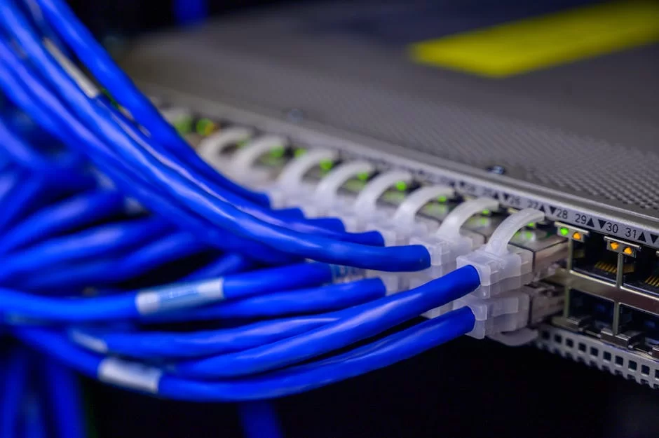
Port security is a basic security feature that caps the number of MAC addresses that can connect to a switch port. For example, you allow only one MAC address on a user port.
Someone could plug a switch into your port and try to hook up many devices. So the system auto-shuts the port. This is vital, mainly in public spots like lobbies or meeting rooms.
Its setup is quite simple: turn on the feature with switchport port-security, set the cap with switchport port-security maximum 1.
You define what happens on a breach with switchport port-security violation shutdown. Also, you can save learned MAC addresses for good with switchport port-security mac-address sticky.
However, you need to be careful when setting this up. On ports with IP phones, due to the phone’s built-in switch, you must allow at least two MAC addresses.
Also, note that to open a port that shut down by mistake, you must apply the shutdown and no shutdown commands in order.
BPDU Guard: Blocking STP Attacks
Spanning Tree Protocol is a vital protocol to stop network loops. Yet an attacker can send BPDU packets from their own device to mess with the STP topology.
BPDU Guard was designed to block these kinds of attacks. When you turn this feature on, the port auto-shuts the moment it gets a BPDU packet.
To set it up, you must apply the spanning-tree bpduguard enable command on client ports. Or, you can auto-turn it on all portfast ports globally with the spanning-tree portfast bpduguard default command. The second method gives management ease, mainly in big networks.
This feature should cause no trouble anywhere besides normal user ports. Yet if you turn it on a trunk port by mistake, you block legit BPDU traffic and can cause loops in the network. So, use BPDU Guard only on access ports.
DHCP Snooping and Dynamic ARP Inspection (DAI)
DHCP snooping is a security machine that spots and blocks unauthorized DHCP servers on your network. The switch sorts ports as trusted and untrusted.
It only lets DHCP replies (DHCPOFFER, DHCPACK) from trusted ports pass. This way, you stop an attacker from setting up their own DHCP server and steering users to a wrong gateway.
The setup steps are: First, turn on the feature globally with ip dhcp snooping. Then, mark the port where the DHCP server is plugged as trusted with ip dhcp snooping trust.
Last, turn on snooping on the user VLANs with ip dhcp snooping vlan 10,20,30.
Dynamic ARP Inspection (DAI) works hand in hand with DHCP snooping. It checks ARP packets using the IP-MAC binding table DHCP snooping builds.
It auto-drops invalid ARP replies. This way, you fully block ARP poisoning attacks. To turn on DAI, you can use the ip arp inspection vlan 10,20,30 command.
The step-by-step setup order for Layer-2 security:
- First, turn on DHCP snooping globally:
ip dhcp snooping - Mark trusted ports:
interface g0/1,ip dhcp snooping trust - Turn on snooping on user VLANs:
ip dhcp snooping vlan 10,20 - Turn on DAI on the same VLANs:
ip arp inspection vlan 10,20 - Apply port security to access ports:
switchport port-security - Turn on BPDU guard:
spanning-tree bpduguard enable - Verify:
show ip dhcp snooping,show ip arp inspection
Further Reading Resources for VLAN Networks
To dig deeper into the topics we covered in this guide, I suggest you check the official sources below. These sources give the most current standards and academic bases of the topic.
- IEEE 802.1Q Standard: This is the IEEE document containing the formal definition of the VLAN tagging machine. It is the most authoritative source on frame structure, PCP coding details, and protocol behavior.
- IETF RFC 7348 (VXLAN): This is the IETF document setting the basic definition and encapsulation structure of VXLAN. Network experts standardize VNI assignment and VTEP discovery. What’s more, they clarify the data plane operation here.
- Cisco Catalyst 9000 Series VLAN Setup Guide: This is the official setup guide for Cisco’s current hardware. It covers advanced topics like SD-Access integration and TrustSec SGT.
FAQ on Network Segmentation and VLAN Technology
What is the difference between a VLAN and a subnet?
What is VLAN hopping and how do you stop it?
Is a managed switch a must for VLANs?
Why should the Native VLAN be changed?
Is a Layer 3 switch needed for Inter-VLAN routing?
Can I use VLANs on my home network? Which devices support it?
What should I do if two computers in the same VLAN can’t see each other?
Is VTP (VLAN Trunking Protocol) secure?
What is VXLAN, and how does it differ from VLAN?
How do you capture and analyze VLAN traffic with Wireshark?
What is Private VLAN (PVLAN)? When is it used?
What is DHCP Relay? Why is it used?
What is a broadcast storm, and how does a VLAN stop it?
Why should VLAN ID 1 not be used?
What are the most common VLAN setup mistakes?
Conclusion: The Ultimate VLAN Setup Checklist and Best Practices
We have come to the end of this full journey. Now it’s time to turn everything we’ve learned into an actionable checklist. This list will guide you whether you build a new network or audit an existing one. Make sure you apply each item.
Remember, network segmentation is not a one-time project but an ongoing process. As workloads shift and new threats pop up, you must check and update your setup.
A network security policy must be a living document. Also, logging all changes and taking regular backups saves lives in disaster recovery scenes.
Check the checklist below before and after every VLAN setup. This list is the distilled essence of 20 years of field work. Each item formed as a result of a problem I faced or a disaster I stopped in the past. I hope it proves just as useful for you.
The Ultimate VLAN Setup Checklist
- VLAN Planning: Document all VLANs (ID, name, IP subnet, gateway, purpose).
- Default VLAN 1: Remove all user ports from VLAN 1.
- Native VLAN: Change the default on all trunks and check that they match.
- Trunk Allowed List: Permit only the needed VLANs to pass.
- DTP: Turn it off on all access ports (
switchport nonegotiate). - Unused Ports: Shut them down and assign to a Black Hole VLAN.
- Port Security: Turn it on all access ports.
- BPDU Guard: Turn it on all access ports.
- DHCP Snooping: Turn it on user VLANs.
- Storm Control: Set a broadcast storm threshold on all access ports.
- Management VLAN: Separate it from user traffic and limit access.
- Documentation and Backup: Back up the config regularly and log changes.

Be the first to share your comment