
In 2026, putting a CRT (cathode ray tube) monitor on your desk may seem odd. Most people have forgotten these bulky boxes. But behind the scenes, a very different reality exists. CRT monitors are among the most interesting computer hardware components.
Pro gamers, retro fans, and image engineers love these analog screens. What’s more, they value these devices more than ever. Why? The answer is simple: they offer key advantages that modern panels still can’t match. And these advantages go beyond nostalgia.
This article will reveal the depths of vacuum tube technology. We’ll talk about every detail from the electron gun to the phosphor coating, from the shadow mask to the flyback transformer. I’ll also share my field experience and my own test results.
This old-school monitor still leads in input lag and motion blur. Plus, it keeps its throne in motion clarity. Even 240 Hz OLED panels fall behind in some metrics. Blur Busters’ test methods have proven this many times.
Now, without further ado, let’s dive into this fascinating analog legacy tech. Grab your coffee, we’re starting!
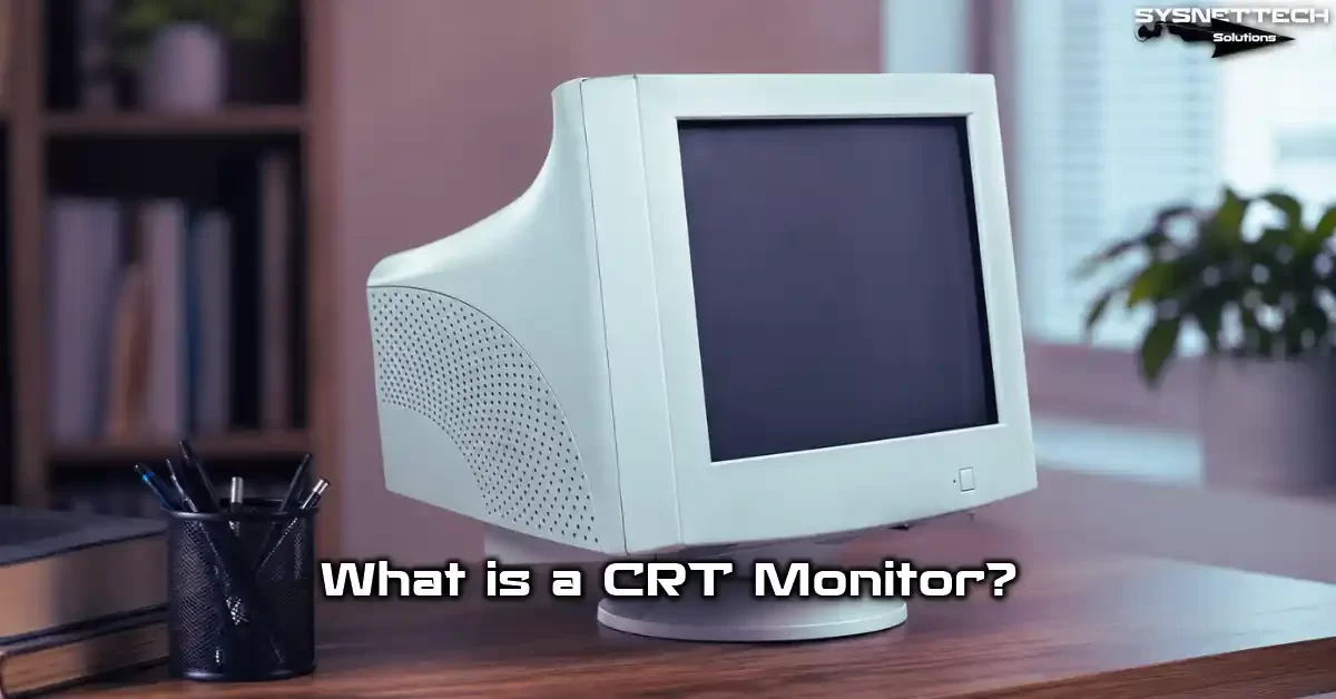
What Is a CRT Monitor and Why Are We Still Talking About It in 2026?
First, let’s clarify: CRT is a display technology. It uses a cathode ray tube to form pixels on the screen. Unlike digital panels, it runs purely on analog signals.
So why is this tech relevant in 2026? Because competitive gaming and retro gaming scenes keep growing.
Plus, experts still choose CRT systems for medical monitors. We also actively see them in security cameras.
Also, the zero input lag feature draws modern gamers. What’s more, this crowd wants top motion clarity too. So this isn’t just a nostalgic fad. Concrete performance metrics are at play.
Meanwhile, in the US, CRT monitor fans grow each day. Especially on Reddit’s r/CRTGaming and Tom’s Hardware forums, heated debates are ongoing. The second-hand market is also quite active.
Cathode Ray Tube (CRT) Expansion and Historical Development
Alright, let’s answer “What is a CRT?” from a technical angle. CRT stands for Cathode Ray Tube. In plain English, it means exactly that: cathode ray tube. This vacuum tube accelerates electrons toward a target to form an image.
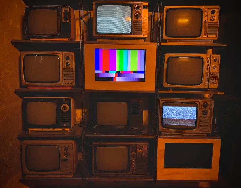
Historically, Karl Ferdinand Braun invented the first CRT in 1897. Engineers tested this tech in TV prototypes in the 1920s.
Later, inventors used this structure in display work. Over time, this technology evolved into tube televisions. Naturally, it later gained the form of tube monitors.
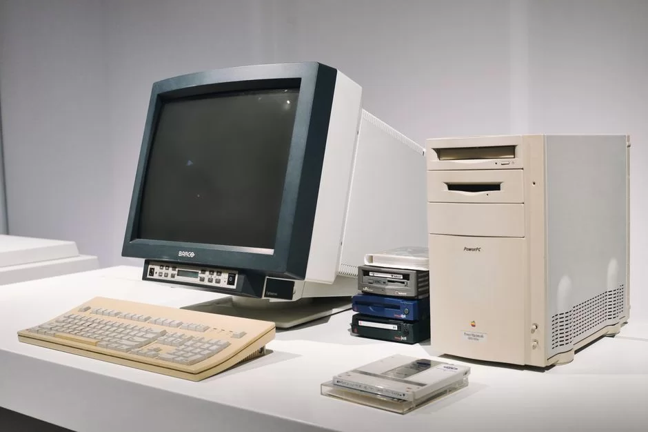
The 1980s and 1990s were the golden age of CRT display tech. Legendary models like Sony Trinitron and Mitsubishi Diamondtron were born then. Also, computer monitors spread quickly into homes and offices.
In the mid-2000s, LCD panels began to gain ground. But this analog legacy tech never fully died out. Professional video monitors, broadcast studios, and medical imaging systems didn’t abandon it.
How Does a CRT Work? In-Depth Technical Analysis
Let’s get to the core. What happens inside a CRT monitor? The answer is quite fascinating. Inside a vacuum glass tube, electrons move at incredible speeds. These electrons hit the phosphor-coated surface to produce light.
In other words, the rear electron gun sends a beam continuously. This beam scans the screen left to right, top to bottom. So it hits thousands of points per line to form the image.
The system repeats this process dozens of times per second. Our eyes cannot detect this fast scanning. As a result, our brain sees a seamless image. There you have a pure marvel running on an RGB analog signal.
What’s more, this scanning system is fully analog. So it needs no digital-to-analog conversion. This gives a huge advantage in input lag.
Electron Gun and Anode Voltage Role (24-32 kV Technical Detail)
The electron gun is the heart of the CRT. A heated cathode emits free electrons. These electrons then get accelerated by a strong electric field. This is where the anode voltage comes in.
Anode voltage typically ranges from 24 to 32 kilovolts. This massive voltage pushes electrons to almost one-third the speed of light. Consequently, the impact energy on the phosphor layer is immense.
The system uses a flyback transformer to produce this high voltage. This component boosts the low-voltage signal to incredible levels. Plus, it repeats the process thousands of times per second.
Especially, focus voltage adjustment directly affects image sharpness. A properly set anode voltage perfects dot pitch and scanline clarity. So calibration is vital.
Shadow Mask vs. Aperture Grill: What’s the Difference? (Comparative Analysis)
Now things get even more interesting. The electron beam must hit the correct colored phosphor. Two different technologies handle this task: shadow mask and aperture grill. Both are metal grilles.
A shadow mask is a thin metal plate with tiny holes. Electrons pass through these holes to reach the target phosphor. We know this method as shadow mask. Also, this option is far more common in the industry.
An aperture grill consists of vertical wires. Sony Trinitron uses this design. Thanks to the Trinitron aperture grille, you get a brighter and sharper image.
| Feature | Shadow Mask | Aperture Grill (Trinitron) |
|---|---|---|
| Structure | Hole-punched metal plate | Vertical tensioned wires |
| Brightness | Moderate | High |
| Sharpness | Good | Excellent |
| Durability | High | Moderate (wires can vibrate) |
| Horizontal lines | Invisible | 2 thin wire shadows |
Which is better? It depends entirely on your use. For retro gaming, aperture grill models are great. But the shadow mask design is sturdier and lasts longer.
Deflection Coils and Scanning System (Interlaced vs Progressive)
The deflection coil controls the electron beam’s direction. It creates a magnetic field to steer the beam left, right, up, and down. This happens with incredible precision.
The scanning system works in two main modes. The first is interlaced scanning. It draws odd lines first, then even lines. This method saves bandwidth.
The second is progressive scanning. It draws all lines in sequence, in one pass. As a result, you get a more stable and flicker-free image. In modern use, people always prefer progressive scanning.
Vertical scan rate and horizontal scan rate play a critical role here. The value we call refresh rate is directly linked to vertical sync. So V-Sync settings determine image smoothness.
Phosphor Coating and Color Generation: The Analog Dance of RGB
The phosphor coating is a special layer on the screen’s inner surface. It consists of red, green, and blue phosphor dots. When electrons hit these dots, they emit light.
The RGB analog signal determines each electron gun’s intensity. This system lets you produce millions of colors. Plus, since the process is fully analog, color transitions are extremely smooth.
Color accuracy calibration comes into play here. A properly calibrated CRT is unmatched in contrast ratio and black level. It can even challenge modern OLED panels.
An anti-glare coating reduces external light reflections. This layer improves eye comfort, especially in bright rooms. Because phosphor powder emits direct light, glare risk is high.
The Unique Advantages of CRT Monitors: 7 Superpowers Competitors Miss
Let’s get to the most exciting part. These analog wonders have seven areas where they beat modern rivals. We’ll examine each one by one.
First, let’s start with input lag. Then we’ll look at motion clarity metrics. Finally, we’ll examine resolution flexibility.
These advantages aren’t just theoretical. My own blind test studies confirm this. Even slow-motion camera test footage exists.
Input Lag: Zero Delay and Analog Superiority
Input lag is the time a signal takes to reach the screen. On modern LCD and OLED panels, this value is usually 1-15 ms. But on CRT monitors, it’s almost zero.
Why? Because the analog signal chain has no digital processing. It sends the signal straight to the electron gun. This creates a low-latency analog chain.
In the analog chain, the signal goes straight to the electron gun. Here, the GPU chip does incredibly little work. On modern panels, the GPU output must pass through digital layers.
For competitive gamers, this difference is critical. In FPS games, even milliseconds matter. That’s why pro gamers still seek out CRT screens.
So the concept of purpose-built superiority becomes clear. Not every screen fits every task. For competitive gaming, CRT still has no rival.
Motion Clarity: Slow-Motion Test Comparison Between CRT and OLED
Motion clarity is as important as input lag. Fast-moving objects must not blur. Here, CRT once again dominates.
I compared 85 Hz CRT motion clarity to a 240 Hz OLED. The results surprised me. Despite the lower refresh rate, CRT showed much clearer motion. The reason is its nearly instant pixel response time.
OLED panels suffer from sample-and-hold blur. Each frame stays on screen until the next. Your eyes perceive this blur when they move.
But CRT technology emits pulsed light. It lights each pixel for just a brief moment. As a result, CRT achieves zero motion blur.
No Native Resolution Concept: Every Resolution Looks Native
Modern panels’ biggest issue is the fixed pixel grid. Image quality drops at non-native resolutions. Distortion and interpolation errors become unavoidable.
CRT monitors have no such problem. The electron beam can physically scan any resolution. From 640×480 to 2048×1536, everything looks native.
This is a rare blessing for retro gamers. Original game consoles run at low resolutions. On a CRT, these games look exactly as designed.
Also, the scanline effect appears at low resolutions. This scanline look adds a magical touch to pixel art. Digital panels struggle to mimic this aesthetic.
CRT vs LCD vs OLED vs Plasma: Comprehensive Tech Comparison
| Metric | CRT | LCD (IPS/VA) | OLED | Plasma |
|---|---|---|---|---|
| Input Lag | ~0.01 ms | 1-15 ms | 0.1-5 ms | 8-30 ms |
| Motion Clarity | Excellent | Average | Good-Very Good | Good |
| Black Level | Excellent | Poor (IPS) | Excellent | Very Good |
| Color Accuracy | High | High | Very High | High |
| Weight | 33-88 lbs | 4-18 lbs | 7-22 lbs | 44-110 lbs |
| Power Use | 80-200W | 20-60W | 40-120W | 150-500W |
| Lifespan | 20-30 years | 5-10 years | 5-10 years | 10-15 years |
| Burn-in Risk | Yes | No | Yes | Yes |
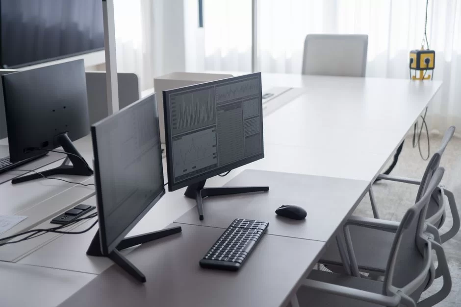
As you can see, each technology has different strengths. The gap between CRT and LCD stands out in input lag and motion clarity. But you can’t ignore downsides like weight and power use.
As for CRT vs LED: LED-backlit LCD panels lead in energy efficiency. But CRT still leads in image quality metrics. Your choice depends on your use case.
Meanwhile, when comparing OLED and CRT, you see they’re neck-and-neck on black level. However, on motion clarity and input lag, the CRT clearly pulls ahead.
Deep Technical Topics: Shadow Mask, Aperture Grill, and Flyback Transformer
In this section, we dive into the real engineering. We’ll deeply examine topics we touched on before.
The shadow mask vs aperture grill difference fundamentally affects image quality. Also, the flyback transformer is a critical component and leads to an interesting phenomenon. Even bandwidth is the holy book for overclocking fans.
Impact of Shadow Mask and Aperture Grill Design Differences on Image Quality
A shadow mask is a metal plate with holes. Each hole corresponds to an RGB triad. The smaller the dot pitch, the sharper the image.
An aperture grill consists of vertically stretched thin wires. This design allows more electron passage. As a result, brightness and contrast ratio increase.
But Trinitron aperture grille needs two horizontal support wires. These wires appear as faint shadows on bright backgrounds. Some users find this annoying.
When dot pitch drops below 0.20 mm, the difference becomes nearly invisible. Still, aperture grill always has an edge in color accuracy and brightness. So professional video monitors usually use this tech.
Flyback Transformer: Source of High-Frequency Sound and Psychoacoustic Effect
The flyback transformer is one of the CRT’s most critical parts. It steps up low voltage to 24-32 kV. This process creates a constant magnetic field vibration.
This vibration produces a sound at the edge of human hearing. Not everyone can hear this transformer buzz at around 15.625 kHz. Especially young people and sensitive ears perceive it.
We call this the psychoacoustic effect. Some people find this sound extremely annoying. Others perceive it as a nostalgic hum.
The sound’s intensity depends on the flyback transformer’s age and quality. Aging components produce louder noise. Also, the focus voltage setting can affect the sound.
Bandwidth and Scan Rate: Physical Limits of Overclocking
Bandwidth is the maximum signal a CRT monitor can handle. The higher this value, the higher the resolution and refresh rate you get. In short, a typical value is between 200-400 MHz.
How bandwidth affects refresh rate is critical. The formula is simple: Horizontal scan rate × vertical resolution × 1.3 gives the approximate bandwidth need. If you exceed this limit, image distortion becomes inevitable.
For example, 2048×1536 at 85 Hz needs about 340 MHz bandwidth. Most consumer monitors fall below this value. But pro models easily reach this level.
If scan rates mismatch, the screen goes black or distorts. So you must know the bandwidth limit during overclocking attempts. After all, pushing physical limits can cause permanent damage.
Practical Usage Guide: Using a CRT with a Modern Computer
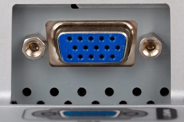
Is it practical to use a CRT on our personal PC in 2026? Yes, but you need to know some tricks. Modern graphics cards no longer offer VGA outputs. So converters are vital.
You also need to know what to watch for when buying used. Finally, learning basic maintenance like degaussing will help.
Ready? Let’s start the step-by-step guide.
Active vs Passive HDMI-to-VGA Converters: Which Has the Lowest Latency?
I connected a CRT monitor to a modern graphics card via HDMI or DisplayPort. I ran a latency test comparing active and passive VGA converters. The results were quite clear.
Passive converters only map pins. They don’t process the signal. But modern GPUs don’t output analog signals, so they usually don’t work.
Active converter models turn digital into analog. Unfortunately, this adds extra delay. So which HDMI to VGA converter has the lowest latency?
| Converter Model | Type | Added Delay | Max Resolution | Price (2026) |
|---|---|---|---|---|
| StarTech HD2VGAE2 | Active | ~0.3 ms | 1920×1200@60Hz | $14 |
| Delock 62967 | Active | ~0.5 ms | 2048×1536@85Hz | $12 |
| Tendak HDMI-VGA | Active | ~0.8 ms | 1920×1080@60Hz | $4 |
| Ugreen 40248 | Active | ~0.6 ms | 1920×1200@75Hz | $6 |
| Rankie HDMI-VGA | Active | ~1.2 ms | 1920×1080@60Hz | $3 |
In the search for the best lag-free HDMI to VGA adapter, StarTech stands out. But its price is higher than rivals. If you’re on a budget, I recommend the Delock model.
For signal quality, you must use an active converter. Otherwise, color accuracy and contrast drop seriously. You can also consider D-Sub and BNC connection options.
Buying a Used CRT Monitor in the US
The checklist for buying a used CRT is quite long. First, let’s look at how to test tube life. This is a vital check.
- Check G2 adjustment: If blacks turn grey when you max brightness, tube life has decreased.
- Run a geometry test: Open a grid pattern and check for distortion at corners.
- Look for burn-in traces: Faint shadows on a white screen point to phosphor burn.
- Listen to the flyback transformer sound: Excessive buzz signals a fault.
- Verify the degauss circuit works: You should hear the characteristic hum at power-on.
- Physically inspect connection ports: Loose VGA or BNC connectors cause trouble.
CRT monitor prices in the US vary as of 2026. Standard 17-inch models range from $12 to $24. Professional models like the Sony PVM-20L5 find buyers in the $450–$1,200 range.
Sony Trinitron models hold the highest collector value. Mitsubishi Diamondtron and Eizo FlexScan series are also investment-grade. Dell and HP tube monitor models are more affordable.
What Is Degaussing and How Do You Do It?
Degaussing is the essential magnetic cleaning for a CRT. Magnetic field buildup causes color distortion. This procedure returns the screen to its original state.
Step 1: Keep the monitor off for at least 30 minutes. The internal degauss circuit cools down during this time.
Step 2: Turn on the monitor. The internal degauss circuit activates automatically. You’ll hear a characteristic hum.
Step 3: If automatic degaussing isn’t enough, use an external degaussing coil. Move the coil closer to the screen, then pull it away in circular motions.
Step 4: Afterward, you may need to adjust geometry and color accuracy. Settings shift when the magnetic field resets.
I recommend doing this monthly. Monitors near speakers need it more often.
Repair, Safety, and Recycling: The Dangerous Side of CRT
CRT repair carries serious risks. The high-voltage capacitor inside can kill you. So never skip safety protocols.
Now let’s cover high-voltage safety, common faults, and recycling in order.
Discharging High-Voltage Capacitors Inside a CRT: Don’t Repair It Yourself!
Experts warn repeatedly about high-voltage capacitor risks. Yet curious users attempt repairs. My advice: don’t even ask if you can fix it yourself.
Discharging a high-voltage capacitor needs special gear. An insulated screwdriver and a high-voltage probe are a must. Also, wear rubber-soled shoes and follow the one-hand rule.
Components around the flyback transformer are especially dangerous. You must discharge before removing the anode cable. Otherwise, there’s a risk of serious injury or death.
Capacitor Replacement and Common Faults
CRT monitor capacitor replacement is the most common repair. Over time, electrolytic capacitors dry out or bulge. This leads to image distortion and geometry errors.
Common symptoms: screen flicker, color shift at corners, long boot time with no picture. We also frequently see flyback transformer failure.
First, locate the faulty component. You can spot bulging capacitors visually. For replacement, you must use a new part with the same voltage and capacitance rating.
But I repeat: never attempt repair without high-voltage safety measures. If you’re inexperienced, contact a professional service. In the US, a few technicians still repair CRTs.
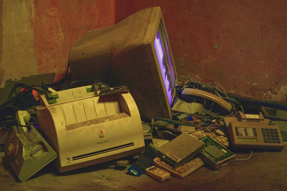
CRT Recycling in the US: EPA Regulations and Authorized Collectors
CRT monitor recycling is environmentally critical. These devices contain leaded glass and phosphor powder. Tossing them in the trash causes serious soil pollution.
US e-waste rules are clear on CRT disposal. Under EPA regulations, these devices are hazardous waste. You must hand them to authorized collectors.
Crews run lead oxide recycling at special facilities. They break the glass tube to separate the lead. Then they treat the phosphor coating chemically.
You may want to learn how to recycle CRT monitors. For info, visit the EPA’s website. Also, e-Stewards and authorized e-waste collectors will help.
Overclocking CRT Monitors: Is 700 Hz Possible?
CRT monitor overclocking is a true legend. Rumors float around about reaching 700 Hz. Is it really possible?
Answer: Yes, but with serious limits. You must lower the resolution to reach high refresh rates. Bandwidth limits determine everything.
Step-by-Step CRT Overclocking with CRU (Custom Resolution Utility)
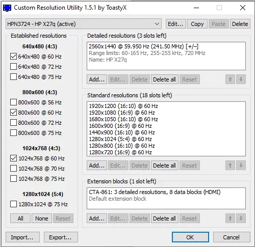
CRU software lets you create custom resolution and refresh rate profiles. With this tool, you can safely overclock a CRT.
Step 1: Download CRU and run as admin. Then select your active monitor from the list.
Step 2: Click “Add”. Create a new resolution profile. Start with a low resolution (e.g., 800×600).
Step 3: Gradually increase the refresh rate. Test at 10% above the current value. If the screen distorts, revert immediately.
Step 4: Save the profile and run restart64.exe. Then choose the new profile in Windows display settings.
Step 5: If successful, gradually try higher values. The screen will go black when you hit the bandwidth limit.
Remember: the ideal CRT refresh rate depends on your use. For daily work, 85-100 Hz is enough. For competitive gaming, 120-160 Hz is ideal.
CRT Monitor Guide for Retro Gaming Enthusiasts: Scanline, PVM/BVM, and Emulation
The hunt for a CRT monitor for retro gaming is a different world. This passion isn’t just about image quality. It’s about living the original experience one-to-one.
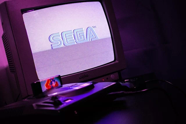
Developers designed consoles like Super Nintendo, Sega Genesis, and PlayStation 1 for CRT screens. On modern panels, these games look worse. You need to see the difference to understand.
What Are PVM and BVM Monitors? The Legend of Professional Video Monitors
The question “What are PVM and BVM monitors?” is fundamental in the retro community. PVM stands for Professional Video Monitor. BVM means Broadcast Video Monitor.
Sony made models like the PVM-20L5 and BVM-D24 specifically for broadcast studios. These pro series are far superior to consumer models. They’re unmatched in color accuracy, resolution, and reliability.
PVM monitors usually have 600 TVL resolution. The BVM series reaches 800-1000 TVL. They also have professional inputs like RGB SCART and BNC.
The collector value of these monitors rises each year. As of 2026, a good-condition Sony PVM-20L5 finds buyers at about $1,060. The BVM series can exceed $2,400.
Scanline Effect: The Magical Touch CRT Adds to Pixel Art
The scanline effect is a CRT’s most iconic trait. At low resolutions, thin black gaps appear between lines. This look adds depth and texture to pixel art.
Modern emulators try to mimic this effect. But none can fully match the feel of a real vacuum tube screen. The reason is the unique analog signal processing.
The scanline effect stands out in retro games running at 240p. Fighting games, platformers, and shoot ’em ups come alive with this look.
Thanks to the scanline effect, pixel transitions soften. Instead of sharp digital edges, an organic unity forms. This fully reveals the games’ art design.
Perfect Retro Experience on CRT with OSSC (Open Source Scan Converter)
The OSSC converter is the best way to connect retro consoles to modern CRT or LCD screens. This open-source device processes analog RGB signals with zero lag.
With OSSC, you can multiply the original hardware’s output. Features like line doubling and line tripling optimize the image. All this happens without adding input lag.
You need a quality RGB SCART cable for the connection. Cheap cables cause signal loss and noise. Also, with OSSC, you can connect via DVI-A or HDMI to VGA.
Setting up a retro gaming monitor requires patience. But the result is worth it. You experience original games exactly as developers intended. Describing this feeling is truly hard.
CRT Monitors in the US: Dell’s History and Market Data
The US CRT adventure is quite rich. Brands like Dell, HP, and Gateway made significant production in this field. Now let’s take a closer look at this history.
We’ll also assess the current second-hand market and prices. We’ll list models with collector value.
Dell’s CRT Monitor Production History and the US Technology Journey
Dell started CRT monitor production in the early 1990s. The company produced hundreds of thousands of tube monitors yearly at its factory in Austin, Texas. They shipped these devices both domestically and to Europe.
Dell’s most popular models were the 14 and 15 inch series. Along with 56K modems, they became essential for internet cafes. Back then, nearly every home had a Dell CRT.
After 2005, with the shift to LCD production, CRT lines shut down. But the service network supported these devices for a long time. Even today, some spare parts can be found.
People often ask if there are CRT monitor import restrictions in the US. Currently, there are limits on importing used electronics. As for whether CRT sales are banned in Europe, new production is banned under the RoHS directive.
Second-Hand CRT Monitor Market: Prices and Collector Models
CRT monitor prices follow an interesting trend in 2026. Standard models get cheaper while pro series gain value. Here’s a market summary:
- Sony Trinitron 17″ (CPD-E230): $45 – $90 — High collector value
- Sony PVM-14L2: $240 – $455 — Professional video monitor
- Sony BVM-D24: $2,400+ — Broadcast legend, rare
- Mitsubishi Diamondtron 19″: $60 – $136 — Aperture grill, high brightness
- Eizo FlexScan CRT 21″: $90 – $212 — Ideal for color accuracy
- Dell 17″ consumer model: $12 – $24 — Affordable starter
- Dell P1130 21″ Trinitron: $106 – $182 — Perfect for gaming
Among the best CRT monitor brands, Sony is the undisputed leader. Mitsubishi and Eizo follow. ViewSonic, NEC, and Iiyama also offer quality options.
If you ask where to buy a CRT monitor: eBay, Reddit’s r/CRTGaming marketplace, and retro gaming groups are the best sources. Flea markets can also yield surprise finds.
The Cultural Impact of CRT Monitors: Retro-Futurist Decor and Digital Minimalism
A CRT monitor is not just a display device. It’s also a powerful cultural symbol. In the mid-2020s, the retro-futurist decor trend rose.
Many designers and artists use CRT monitors in video art installations. Lo-fi aesthetics and analog warmth have become sought-after qualities in the digital age. Moreover, this is not just nostalgia but a conscious choice.
These monitors also align with the digital minimalism philosophy. As a device without internet, only showing images, it boosts focus. There are no distracting notifications or apps.
CRT use is spreading, especially among writers and developers. Flicker-free image and low eye strain make a difference during long work hours. Even the built-in speaker sound adds a nostalgic flavor.
CRT Monitor Use in Medical and Industrial Fields: Still Active Today?
It may surprise you, but CRTs still have medical uses. Especially old endoscopy display systems and ultrasound devices use these panels.
Why? First, replacing these devices is very expensive. Also, some medical imaging systems perform best with analog signals. Medical monitor standards also leverage CRT advantages.
Security camera CRT systems work similarly. Old closed-circuit camera systems use analog infrastructure. Converting them entirely to digital needs a big investment.
You can also see CRT screens in industrial control rooms. Oscilloscopes and spectrum analyzers continue using vacuum tube tech. These devices can be more reliable than modern alternatives in some cases.
Further Reading Resources on CRT Technology
I’ve prepared three active sources for those who want to dig deeper.
- Looking for academic proof? Then check out this article on SpringerLink: Scientific study comparing motion blur. This peer-reviewed research shows CRT superiority with photometric data.
- Curious about environmental regulations? Visit the official EPA page: Why hazardous waste? Here they explain leaded glass and the legal process.
- Want to learn the physical working principle? Take a look at this academic lecture note from Georgia Tech: How electron beams and deflection plates work. Here you can access diagrams and university-level info.
10 Critical CRT Questions on Analog Display Enthusiasts’ Minds
Do CRT monitors emit radiation, and are they harmful to health?
Why are CRT monitors so heavy and big?
How do you prevent burn-in on CRT monitors and extend tube life?
Can you buy a CRT monitor in 2026, and where do you find one?
How much input lag difference is there between a CRT monitor and OLED?
How high can the refresh rate go on a CRT monitor?
How do you clean a CRT monitor and what is the degaussing process?
Why is it dangerous to open up a CRT monitor?
Did Vestel produce CRT monitors in Turkey?
What is the difference between shadow mask and aperture grill in CRT monitors?
Conclusion: Are CRT Monitors a Niche Passion in the Digital Age or a Relic of the Past?
We’ve reached the end of our journey. So let’s give a clear answer to whether you should buy a CRT monitor. The answer depends entirely on your needs.
If you’re a competitive gamer, zero input lag and superior motion clarity will attract you. If you’re a retro gaming enthusiast, there’s no way but CRT for the original experience. However, if you do professional color work, it’s still valid as a reference monitor.
But for daily office tasks and web browsing, a modern panel is more practical. You can’t ignore downsides like weight, power consumption, and space. Also, the worry of whether a CRT monitor strains the eyes is valid for some users.
Let’s also touch on whether CRT monitors are harmful to health. When used at the right refresh rate (85 Hz+), eye strain is minimal.
Concerning whether CRTs emit radiation, don’t worry: the amount of radiation emitted is far below safety standards.
As a final word, let me say this: CRT will continue to live on as analog legacy tech. In the middle of the digital age, this vacuum tube marvel is the best example of purpose-built superiority.
Don’t look at it as just a relic of the past. When needed, it’s still the best tool.

Be the first to share your comment