In this article, we will examine the steps of configuring Cisco Switch on a small network topology with Graphical Network Simulator-3.
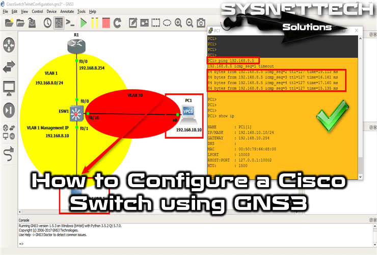
How to Configure a Cisco Switch with GNS3
Cisco Switches are divided into Layer2 and Layer3. Switches operating in OSI Layer2 enable computers to communicate using MAC address tables. In addition, Layer2 Switches are VLAN capable.
Computers send MAC (ethernet frame) frames on a network, and Switches in the environment create MAC address tables. By using switches in the network environment, broadcasts are avoided, thereby increasing performance in network traffic.
Those who prepare for Cisco CCNA exams are familiar with GNS3 or Cisco Packet Tracer programs.
You can configure many of Cisco’s network devices using these programs.
How to Use Basic Cisco Switch Commands
The most specific way to configure a Switch is to use the Graphical Network Simulator software. With this program, you can use network devices more realistically.
Step 1
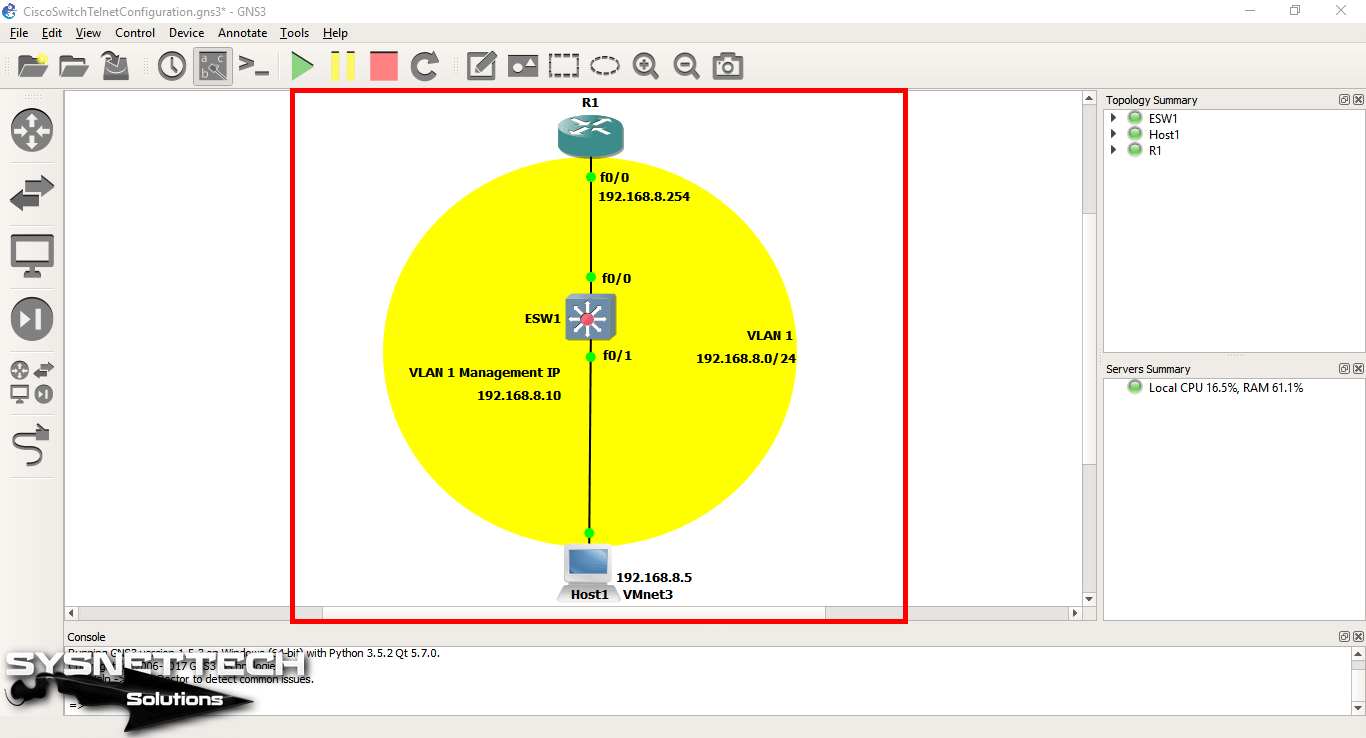
First, run the GNS3 program, and create a new project. Afterwards, create a topology as in the image below.
In this topology, we have used the Layer 3 Switch, which works in the Network layer of the OSI layer.
Step 2
When configuring the Switch for the first time, we usually connect and configure a computer.
Therefore, you must use Telnet to configure the Switch with a remote connection from a PC on the network. Because you don’t have to be near the Switch all the time.
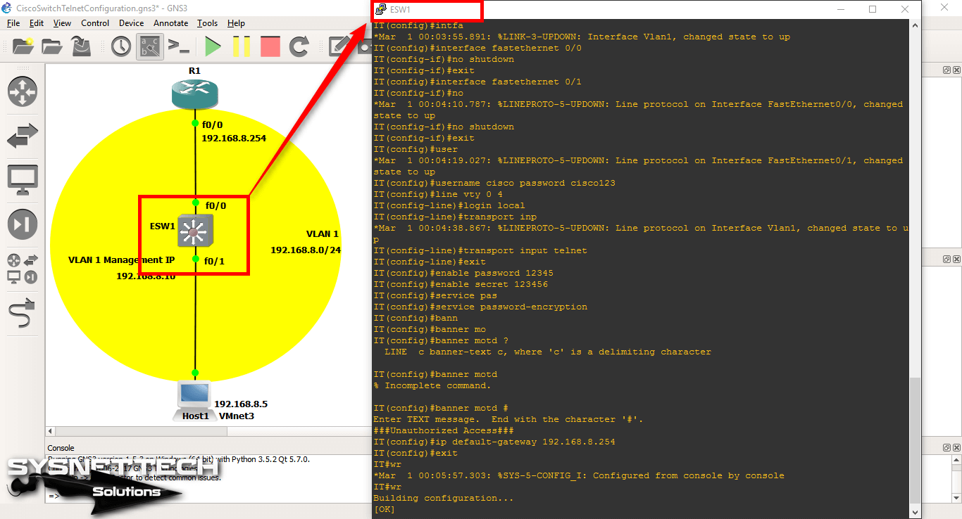
Now, to configure Switch’s hostname, telnet settings, and passwords, execute the following commands at the command prompt.
ESW1# conf t
ESW1(config)# hostname IT
IT# conf t
IT(config)# interface fastethernet 0/0
IT(config-if)# no shutdown
IT(config-if)# exit
IT(config)# interface fastethernet 0/1
IT(config-if)# no shutdown
IT(config-if)# exit
IT(config)# username cisco password cisco123
IT(config)# line vty 0 4
IT(config-line)# login local
IT(config-line)# transport input telnet
IT(config-line)# exit
IT(config)# enable password 12345
IT(config)# enable secret 123456
IT(config)# service password-encryption
IT(config)# banner motd #
Enter TEXT message. End with the character '#'.
###Unauthorized Access###
IT(config)# ip default-gateway 192.168.8.254
IT(config)# end
IT# wr
To assign IP addresses to switches, you must configure the VLAN’s management interface. Execute the following command to assign an IP address to the default VLAN1.
IT# conf t
IT(config)# interface vlan1
IT(config-vlan)# ip address 192.168.8.10 255.255.255.0
IT(config-vlan)# no shutdown
IT(config-vlan)# end
IT# wr
Step 3
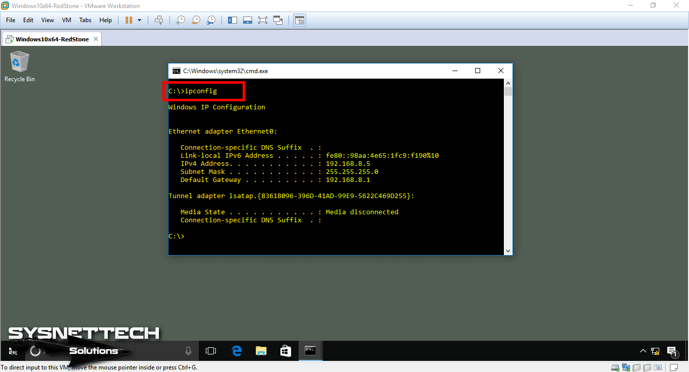
After adding and running the virtual machine to the network topology, check the TCP/IP settings with the ipconfig command on the CMD prompt. If you have not configured the topology, configure the virtual machine as follows.
Step 4
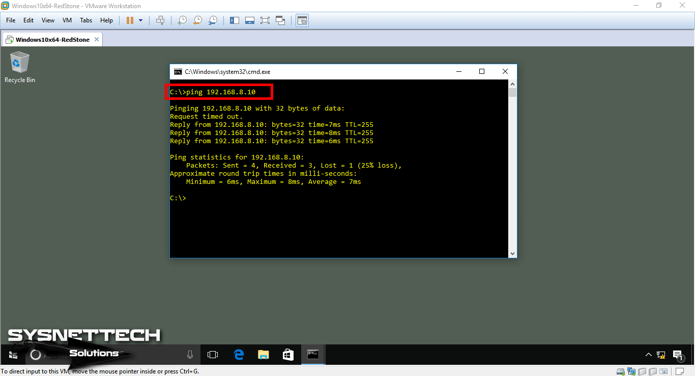
Now test the connection by pinging the VLAN’s management interface from the VMware virtual machine.
Step 5
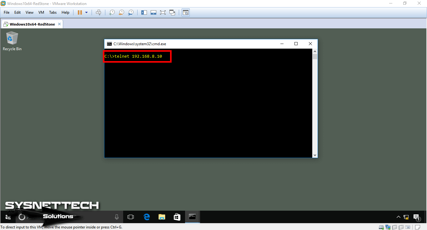
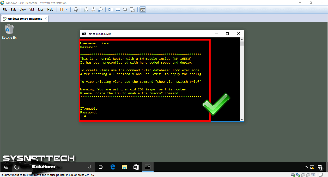
To make a telnet connection from the virtual computer to the Switch’s VLAN1 management interface, execute telnet 192.168.10.10 at the CMD prompt.
Step 6
In step 2, we created a new user for the Switch. Now enter the user name and password you created for the telnet connection.
How to Create a New VLAN in Cisco Switch
The use of VLANs in a network provides a more organized configuration. Therefore, you can create different VLANs for departments such as accounting, IT, and then provide routing between them.
Now, follow the steps below to create a VLAN.
Step 1
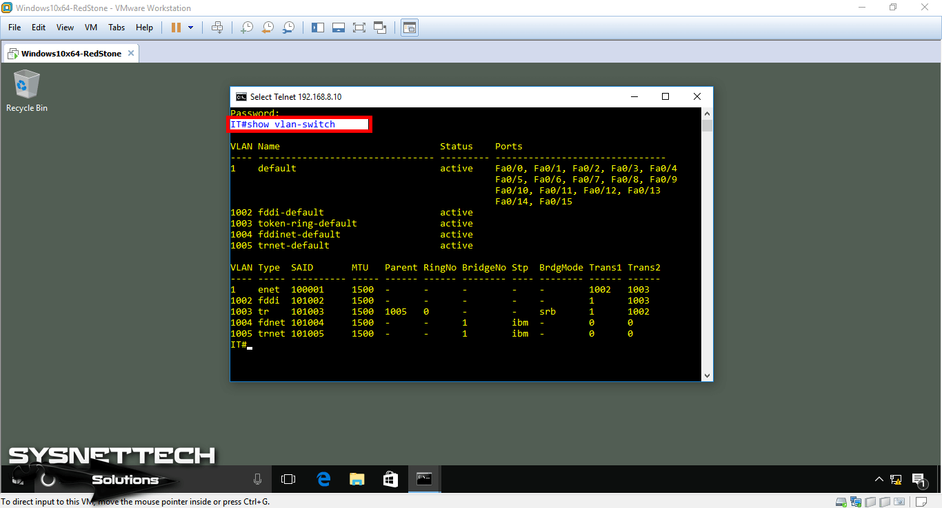
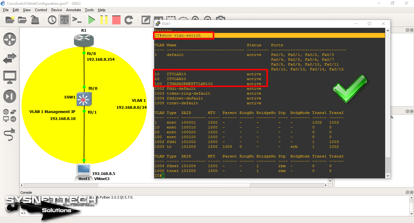
You can check the existing structure using the show vlan-switch command in privileged mode on the switch.
When you look at the image below, you can see that the default VLAN number is 1.
Step 2
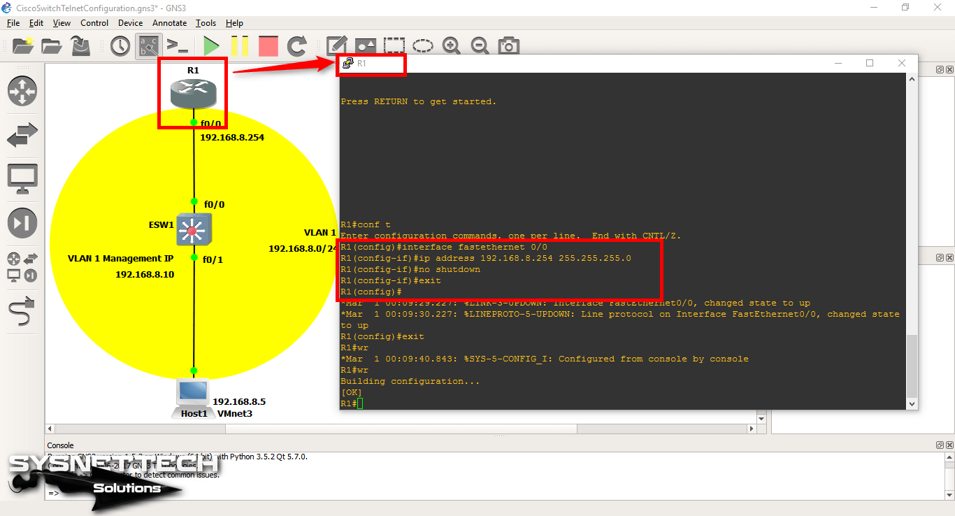
Now open the CLI prompt of the Cisco Router and configure the FastEthernet 0/0 interface and turn on the interface with no shutdown command.
R1# conf t
R1(config)# interface fastethernet 0/0
R1(config-if)# ip address 192.168.8.254 255.255.255.0
R1(config-if)# no shutdown
R1(config-if)# exit
R1(config)# exit
R1# wr
Step 3
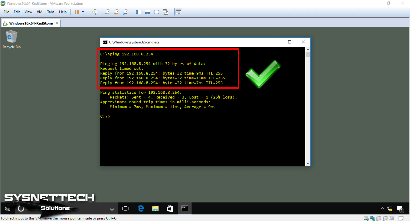
If you ping the Router’s FastEthernet0/0 interface from the VM, you can see that this is successful.
Step 4
Now, to create a VLAN on the Switch, open the CLI console and perform the following commands in sequence.
In addition, make sure you are in Switch’s privileged mode.
IT# vlan database
IT(vlan)# vlan 10 name ITVLAN10
VLAN 10 added:
Name: ITVLAN10
IT(vlan)# vlan 20 name ITVLAN20
VLAN 20 added:
Name: ITVLAN10
IT(vlan)# vlan 100 name ITMANAGEMENTVLAN100
VLAN 100 added:
Name: ITMANAGEMENTVLAN100
IT(vlan)# exit
APPLY completed.
Exiting....
IT#

Step 5
In the CLI console, execute the show vlan-switch command and check the VLANs you have created.
Step 6
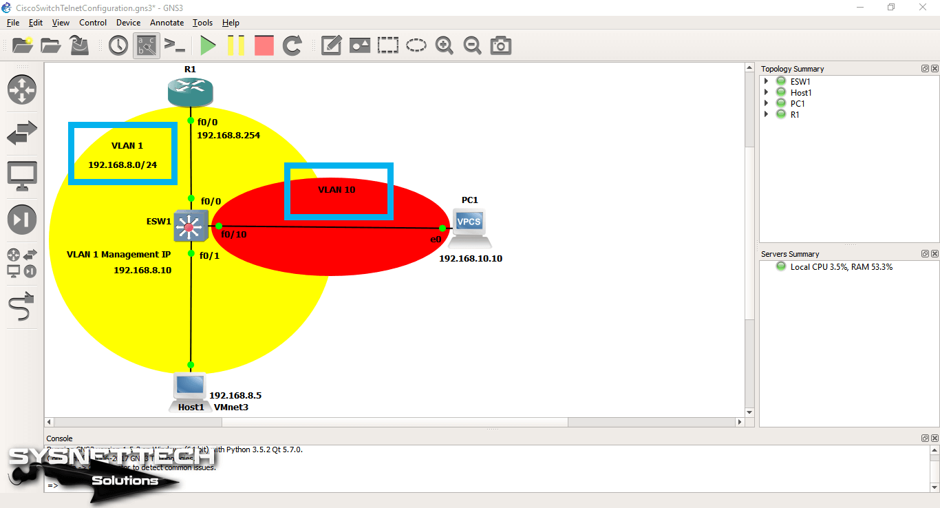
Add one VPCS to the GNS3 workspace as follows. Connect the VPCS to the Switch’s FastEthernet0/10 interface.
Step 7
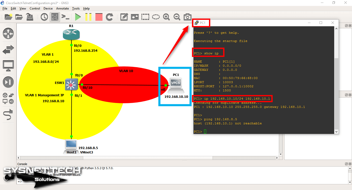
Open the PC1 CLI console, assign the IP address to the VPCS.
Step 8
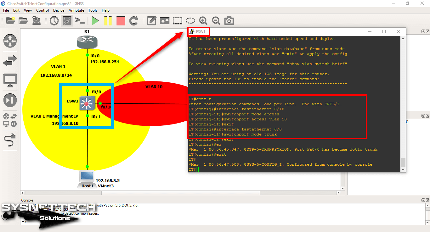
To make VPCS a member of a VLAN, you must first configure the port to which connected to a VLAN.
Connect the VPCS to the Switch’s FastEthernet0/10 interface, and then execute the switchport access vlan 10 command to make this interface a member of the VLAN10.
At the same time, you must configure TRUNK on the interface that connects to the Cisco Router in order to communicate with all VLANs.
IT# conf t
IT(config)# interface fastethernet 0/10
IT(config-if)# switchport mode access
IT(config-if)# switchport access vlan 10
IT(config-if)# exit
IT(config)# interface fastethernet 0/0
IT(config-if)# switchport mode trunk
IT(config-if)# exit
IT(config)# end
IT# wr
Step 9
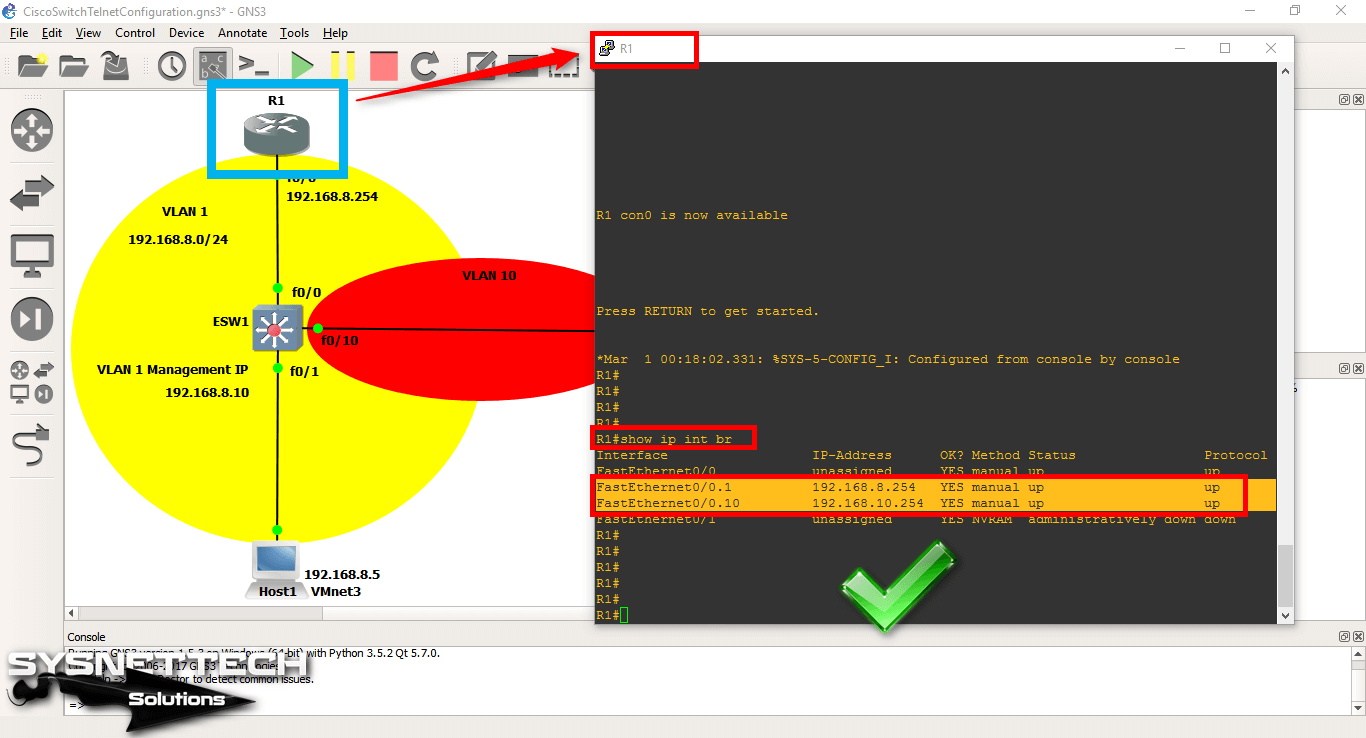
To create a Subinterface on the Router for communication of VLANs, perform the following commands in order.
As you can see in the commands below, 0/0.1 and 0/0.10 subinterface created. Please note that the values may vary. Here, the subinterface created according to VLAN numbers.
R1# conf t
R1(config)# interface fastethernet 0/0
R1(config-if)# no ip address
R1(config-if)# exit
R1(config)# interface fastethernet 0/0.1
R1(config-if)# ip address 192.168.8.254 255.255.255.0
R1(config-if)# encapsulation dot1Q 1
R1(config-if)# exit
R1(config)# interface fastethernet 0/0.10
R1(config-if)# ip address 192.168.10.254 255.255.255.0
R1(config-if)# encapsulation dot1Q 10
R1(config-if)# exit
R1(config)# end
R1# wr

Step 10
Check the interfaces by using the show vlan-switch command on the SW.
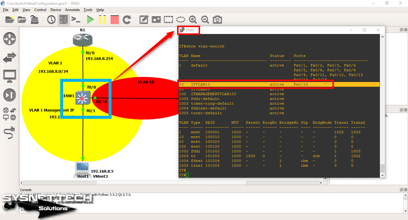
Step 11
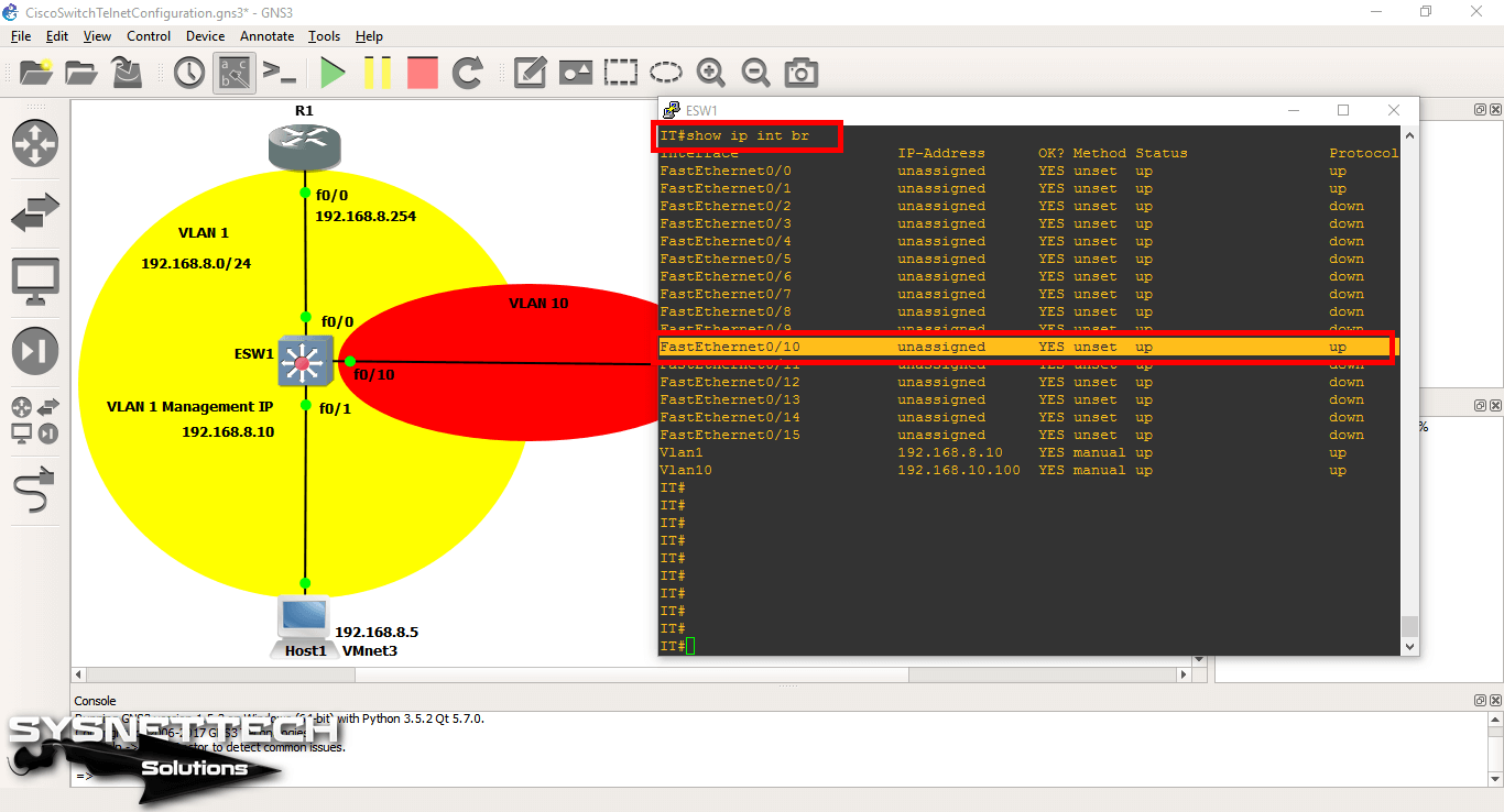
When you check the status of the interfaces with the show ip interface brief command, you can see that the ports are open.
Step 12
You can also control the router interfaces with the same command.
Step 13
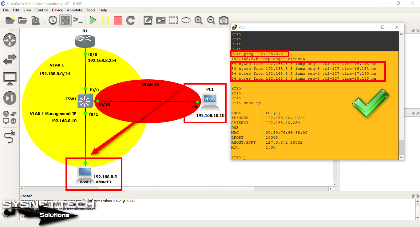
When you ping the VMware PC via VPCS, you can see that the operation was successful.
Step 14
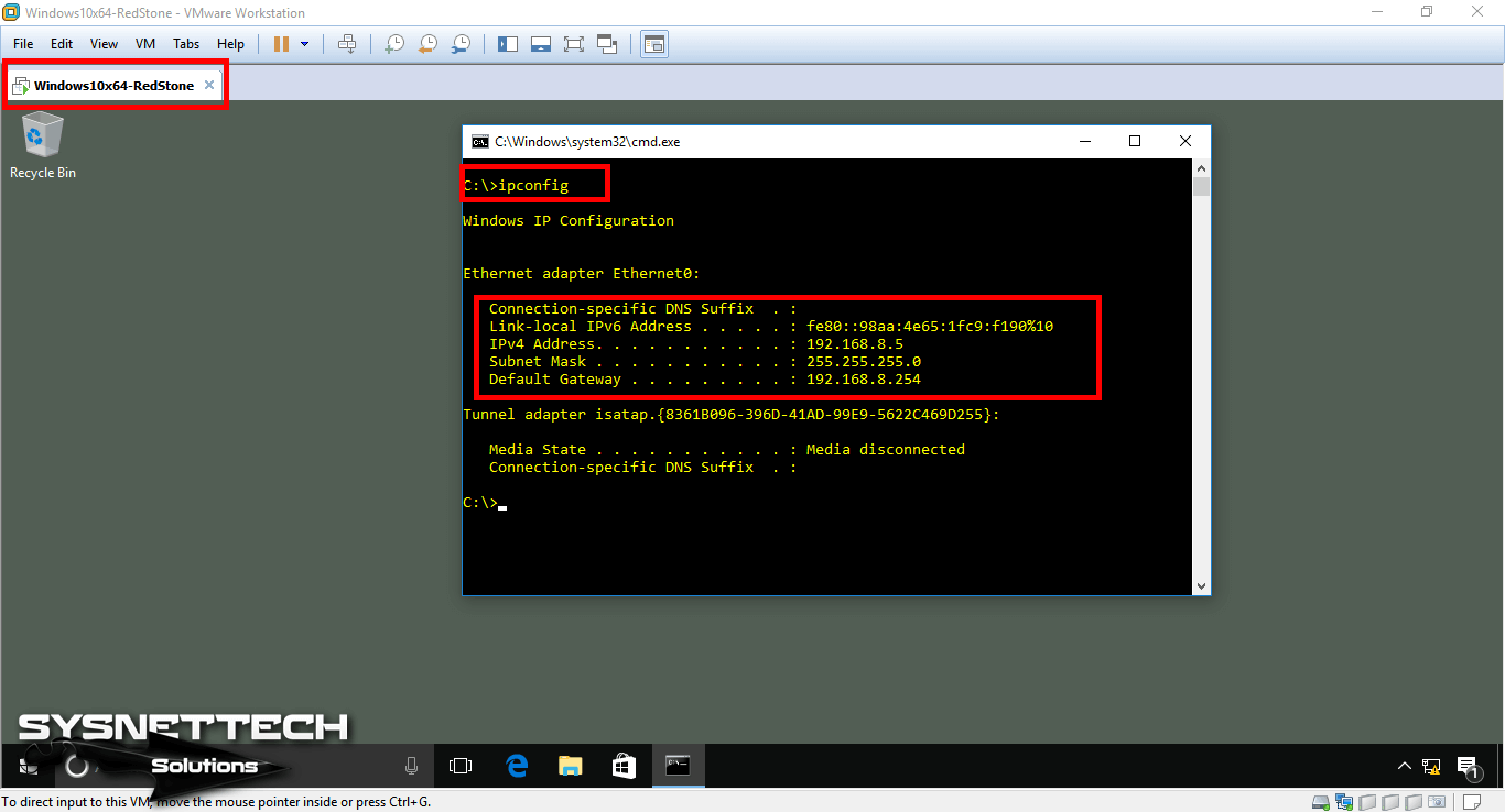
Use the ipconfig command on the CMD to check that you have configured the TCP/IP settings of the virtual machine according to the network topology.
Step 15
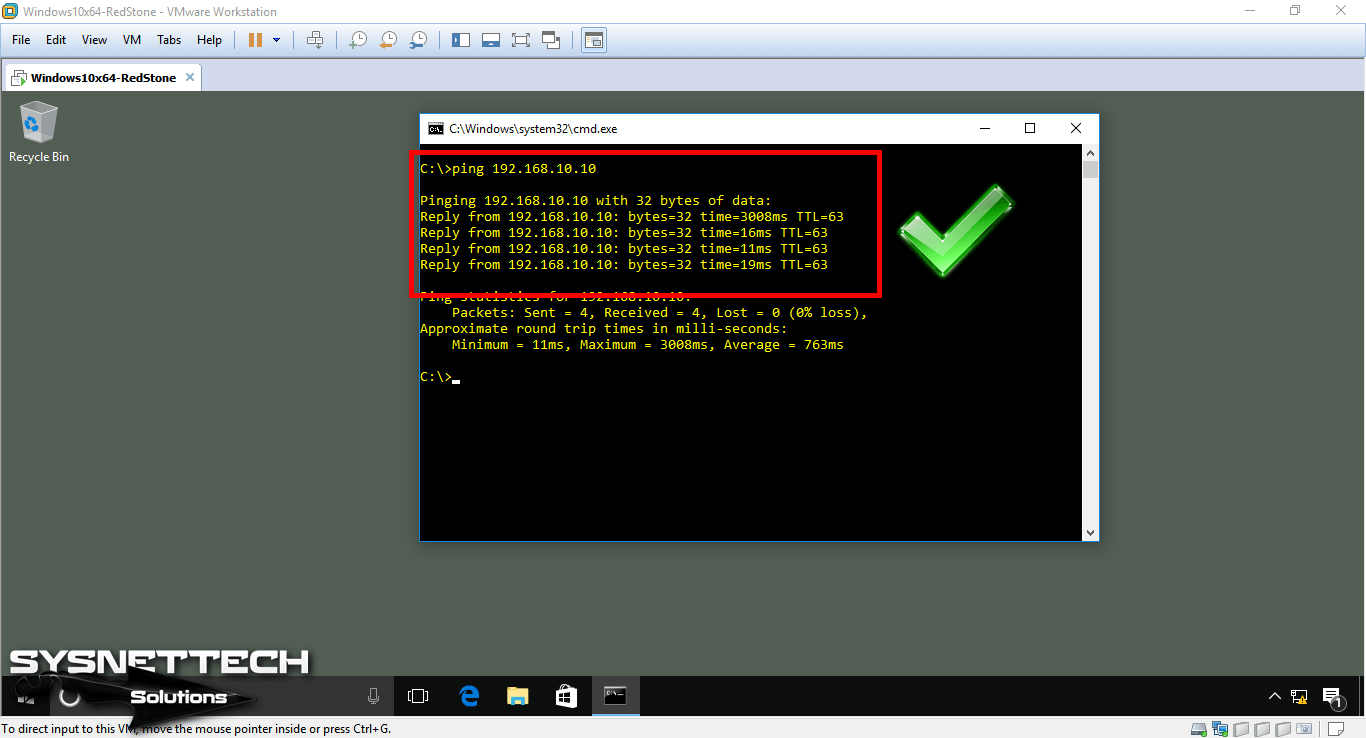
Likewise, when you ping the VPCS from the VM, you can see that the operation was successful.
Configuration Commands
ESW1# conf t
ESW1(config)# hostname IT
IT# conf t
IT(config)# interface fastethernet 0/0
IT(config-if)# no shutdown
IT(config-if)# exit
IT(config)# interface fastethernet 0/1
IT(config-if)# no shutdown
IT(config-if)# exit
IT(config)# username cisco password cisco123
IT(config)# line vty 0 4
IT(config-line)# login local
IT(config-line)# transport input telnet
IT(config-line)# exit
IT(config)# enable password 12345
IT(config)# enable secret 123456
IT(config)# service password-encryption
IT(config)# banner motd #
Enter TEXT message. End with the character '#'.
###Unauthorized Access###
IT(config)# ip default-gateway 192.168.8.254
IT(config)# end
IT# wr
IT# vlan database
IT(vlan)# vlan 10 name ITVLAN10
VLAN 10 added:
Name: ITVLAN10
IT(vlan)# vlan 20 name ITVLAN20
VLAN 20 added:
Name: ITVLAN10
IT(vlan)# vlan 100 name ITMANAGEMENTVLAN100
VLAN 100 added:
Name: ITMANAGEMENTVLAN100
IT(vlan)# exit
APPLY completed.
Exiting....
IT#
IT# conf t
IT(config)# interface fastethernet 0/10
IT(config-if)# switchport mode access
IT(config-if)# switchport access vlan 10
IT(config-if)# exit
IT(config)# interface fastethernet 0/0
IT(config-if)# switchport mode trunk
IT(config-if)# exit
IT(config)# end
IT# wr
R1# conf t
R1(config)# interface fastethernet 0/0
R1(config-if)# no ip address
R1(config-if)# exit
R1(config)# interface fastethernet 0/0.1
R1(config-if)# ip address 192.168.8.254 255.255.255.0
R1(config-if)# encapsulation dot1Q 1
R1(config-if)# exit
R1(config)# interface fastethernet 0/0.10
R1(config-if)# ip address 192.168.10.254 255.255.255.0
R1(config-if)# encapsulation dot1Q 10
R1(config-if)# exit
R1(config)# end
R1# wr
PC1> ip 192.168.10.10/24 192.168.10.254
Switch Configuration Commands ⇒ Video
You can watch the video below to use the basic commands of a Switch and also subscribe to our YouTube channel to support us!
Final Word
In this article, we have examined the simplest configuration steps of a Switch. In our next articles, we will explore more comprehensive projects. Thanks for following us!
Final Word
♦ How to Configure GNS3
♦ How to Configure GNS3 in Ubuntu
♦ How to Create VLAN
♦ Port Security
♦ Static Routing

