Selecting the main bridge in a network is a big job because it decides how things talk to each other in the network. Cisco Packet Tracer is a vital tool that helps network engineers practice different network situations.
In this article, we will talk about how to choose the main bridge using the “Root Primary” command in Packet Tracer. This command is an easy but good way to figure out which bridge is the main one in a network. So, let’s look closely at this topic and understand it better.
How to Configure Root Bridge with Root Primary on Cisco Switches
When we choose Cisco Switches for the root bridge in the network, we usually adjust the Priority command. In our last article, we went over the steps to set up the root bridge. In this article, we will pick the bridge using the “Root Primary” command.
You can set up a backup switch (auxiliary) to do this job if the primary bridge switch is not working. Usually, you can also decide on the backup RB switch in the network distribution layer by using the Priority value.
Now, let’s make a simple network setup for this using the Cisco simulator program. After that, let’s use the “Spanning Tree Vlan (Vlan Number) Root Primary” command on the switches. At this point, we will pick the switch to be the root bridge with this command. In fact, in this process, we manually assign the devices a task.
Steps:
Step 1
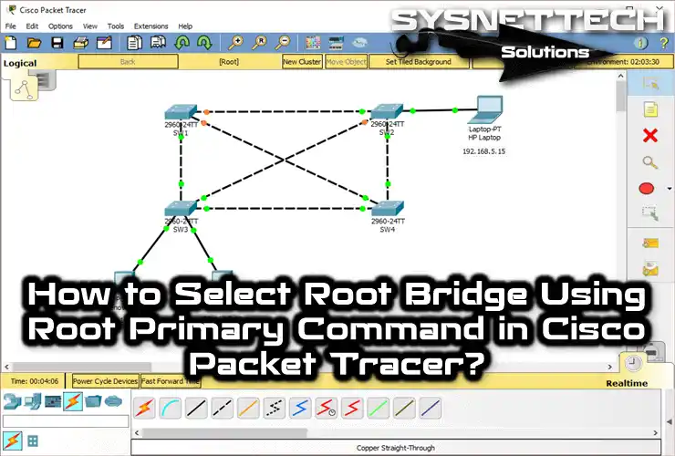
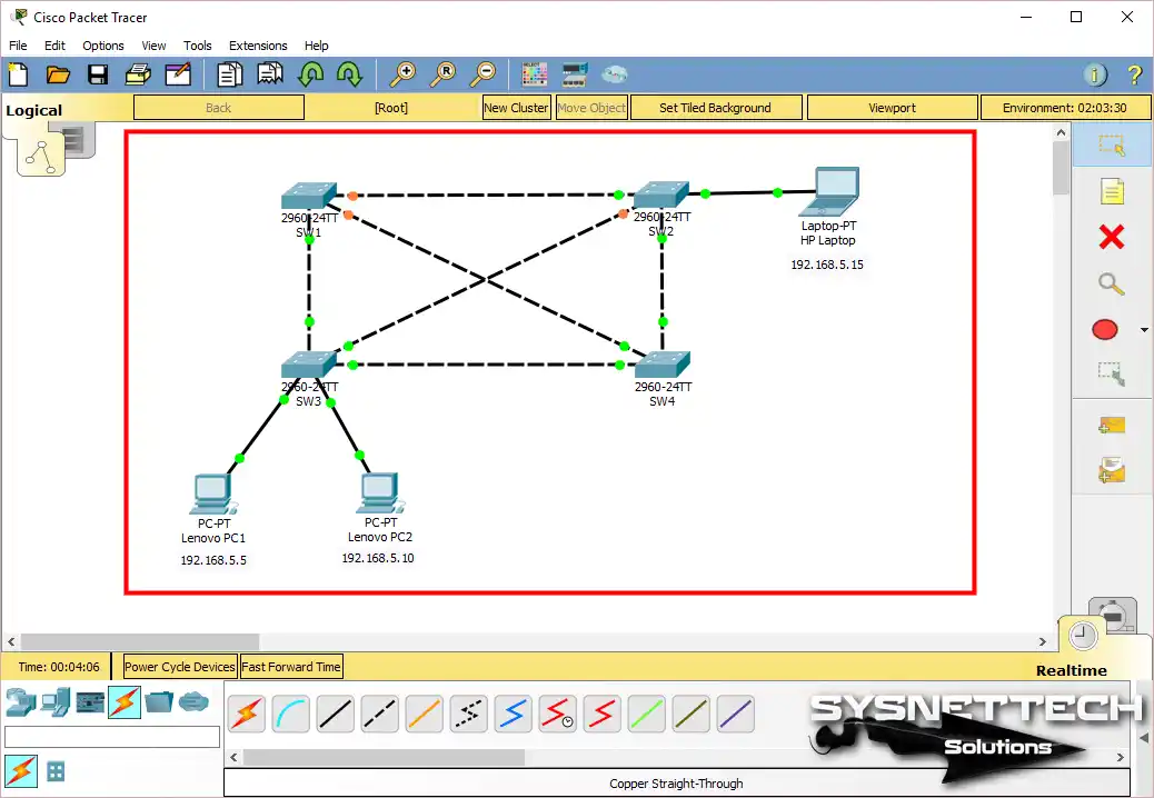
Now, in the image below, you can see that there are 4 Switches (SW) in the network environment. Each of the SWs is interconnected. In this case, you can understand that a redundant structure exists.
Before you start, add 4 Cisco Switch 2960s to the work canvas. Plus, add 2 PCs and 1 Laptop. You can determine the IP addresses of these devices yourself.
However, to follow our guide, do as follows. That is, assign IP addresses 192.168.5.5 and 192.168.5.10 to the PCs. Finally, give the number 192.168.5.15 to the Laptop-PT device.
Step 2
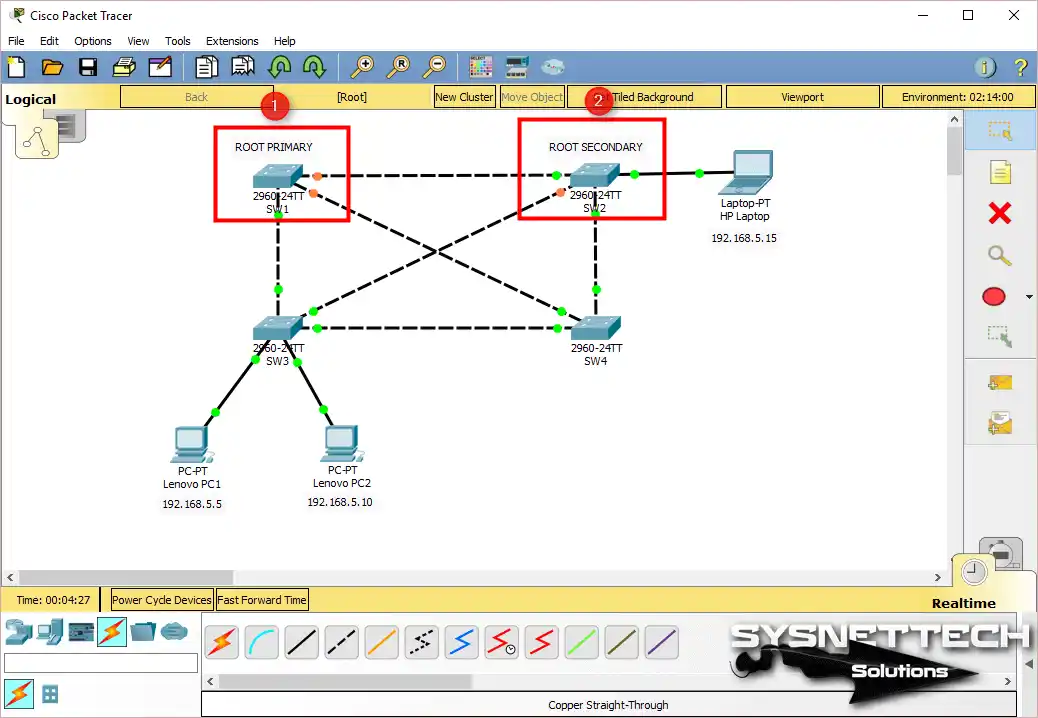
First, connect SW1, SW2, SW3, and SW4 in the work area. Then wire SW1 and SW4, as well as SW3 and SW2, by cross-connecting them. Additionally, connect the PCs to the Switches as shown in the current image.
Now, you need to choose a switch to be the root bridge based on your network setup. In massive company networks, it helps to plan your LAN smartly. So, treat virtual devices just like they’re real ones. Now, decide which switches you want to be the main (PRIMARY) and backup (SECONDARY).
Step 3
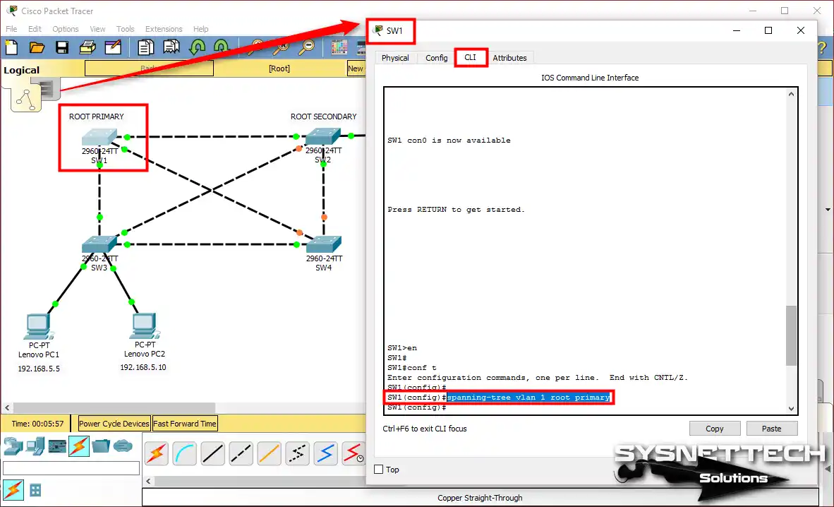
If you want to set the Switch SW1 network device as PRIMARY, open the CLI first. Then, execute the spanning-tree vlan 1 root primary command in the config section.
SW1>en
SW1#conf t
SW1(config)#
SW1(config)#spanning-tree vlan 1 root primary
Step 4
Now, you need to verify that the SW1 device is Root Bridge. In short, for this process, you need to run the show spanning-tree command on the privileged mode.
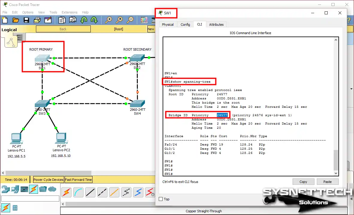
See the show spanning-tree output above. Here, you can see that the Cisco Switch, i.e., SW1, is the Root Bridge. To summarize, we did not change the Priority value of the device. We used the shorter method, the Root Primary command.
Step 5
We determined the root device. Now, let’s set up the SECONDARY device.
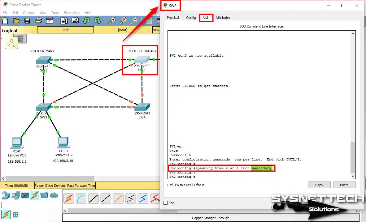
In the Packet Tracer network topology, we designated SW2 as a backup. Now, execute the Root Secondary command in the CLI to configure SW2.
SW2>en
SW2#conf t
SW2(config)#spanning-tree vlan 1 root secondary
Step 6
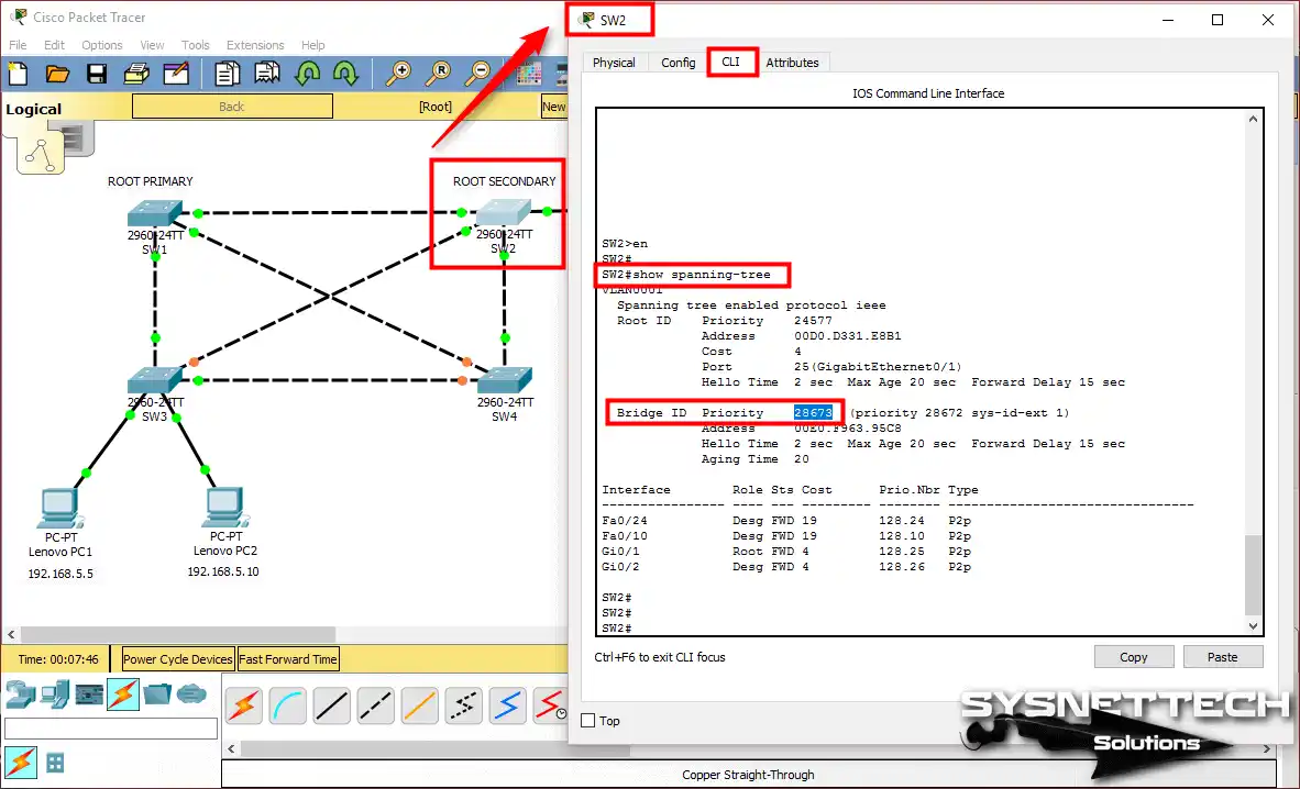
This time, let’s look at the settings of SW2. Run the show spanning-tree command at the CLI command prompt. This time, you will not see the “This bridge is the root” message.
Check that the priority value is lower. This is because it is a secondary device. That is, the device whose Bridge ID has a low priority value acts as a ROOT BRIDGE.
SW1’s bridge ID value is 24577, and SW2’s is 28673. In this case, the ID value of SW1 is lower, so it is ROOT BRIDGE.
Step 7
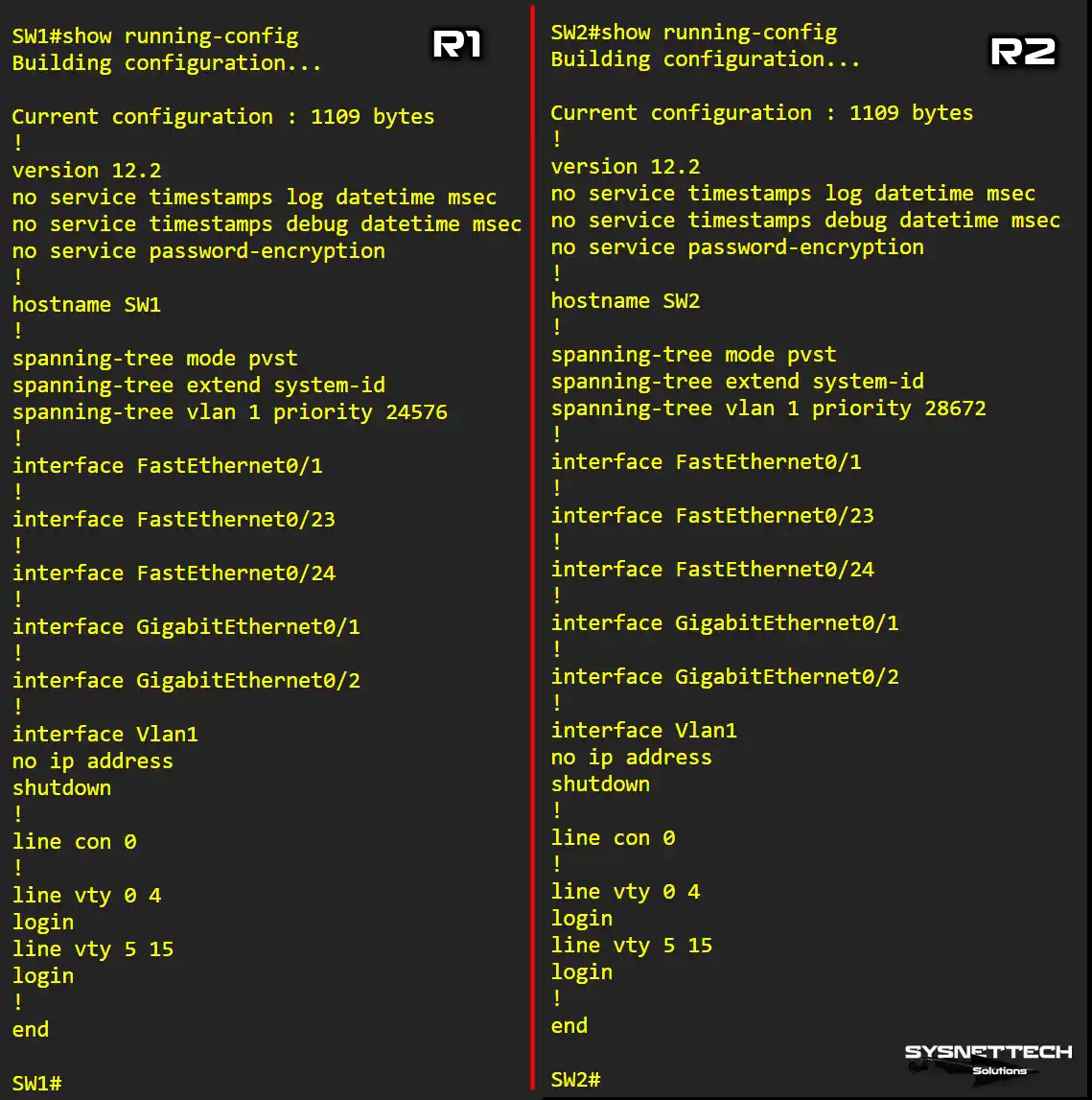
Run show running-config on both configured SWs. As a result, you can more easily determine which one has a lower or higher Priority value.
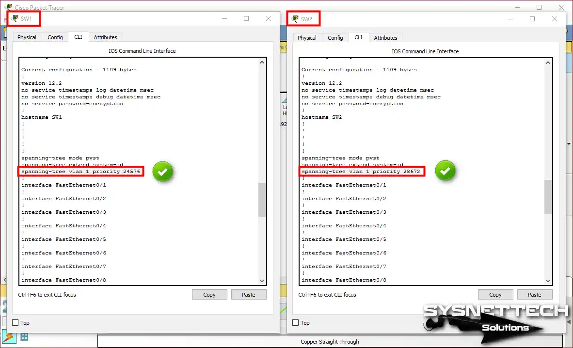
Show Running-Config Output of SW1 and SW2
After setting the Root Bridge, you should check the running configuration in SW1 and SW2. To do this, execute the show running-config command on both devices.
Our YouTube Video for the Root Primary & Secondary Commands
The STP Root Primary and Secondary commands are easy to use. To understand them more, you can watch our training video and subscribe to our YouTube channel!
Conclusion
In summary, knowing about the Root Bridge in Packet Tracer is really important. That’s why we made a good network setup to deal with this. Whether your design is simple or fancy, you have to set up the switches right. One part of this is the Priority value. In a nutshell, it’s crucial to set these values based on your plan.
You can choose which switches are the main (PRIMARY) or backup (SECONDARY) by following the steps in this article. This way, you can make sure your network works well and is reliable. Thanks for reading!
Related Articles
1) Packet Tracer Port Security LAB
2) Packet Tracer TFTP LAB
3) Recovering Packet Tracer IOS
4) Packet Tracer Setup Guide
5) The Review of Root Port, Designated Port, Blocking Port

TolgaBagci
Hi, I'm Tolga, a computer expert with 20 years of experience. I help fix computer issues with things like hardware, systems, networks, virtualization, servers, and operating systems. Check out my website for helpful info, and feel free to ask me anything. Keep yourself in the loop about the newest technologies!